Contact Us
CiiS Lab
Johns Hopkins University
112 Hackerman Hall
3400 N. Charles Street
Baltimore, MD 21218
Directions
Lab Director
Russell Taylor
127 Hackerman Hall
rht@jhu.edu
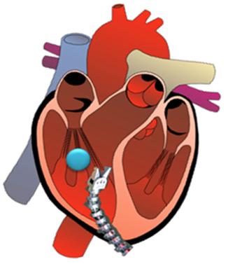
 In case of explosions and various similar incidents, some particles such as shrapnels or bullet fragments can get stuck in the heart and impede cardiac function. The conventional approach is removal of the foreign body through open heart surgery, which comes with high perioperative risk and long recovery time.
To solve this problem, a minimally invasive surgical system is proposed for removing the foreign objects from a beating heart. Also it is claimed that, using this approach can reduce the mortality risk, improving postoperative recovery, and potentially reduce operating room times.
With the aim of solving this problem, the first thing to do is the integration of LARS Robot and Snake Robots in physical and software environments.
In this phase of the project that is summarized above, the aim is to integrate the LARS robot and Snake robot in the fashion shown on the above figure. So far both LARS robot and Snake robot are working on their own environments such that LARS and Snake Robots are accessible only in WINDOWS environment and RTLinux environment respectively.
In gathering information about the current LARS system Teleoperation of LARS Robot project proposal materials will be used. This project materials may be used to come up speed with current status of LARS software.
The specific aims of the project can be listed as below:
In implementing the integration of two robots the following procedures will be followed:
Below the integration scheme can be seen in detail.
* Software Overview
To maximize portability and maintenance between the LARS and LARSnake code base, the organization of classes, tasks, and task interfaces for the LARSnake Application is little changed from the original LARS code. A simplified overview of its structure is provided in Figure 3, showing the major task and class names and the task interface. In the below class structure, red boxes shows the tasks and the task interfaces are drawn as arrows between the tasks. A “required” interface is represented by the tail of an arrow, whereas the head of an arrow represents a “provided” interface. Provided interfaces are those which provide the capability for objects resident at that interface to be read or modified by an outside task. Required interfaces are those which connect to a provided interface of the same type, allowing the required interface to access specified objects of the provided interface. Thus, data flow travels in both directions, but communication is always initiated from the required interface side.
Since in the LARS Teleoperation project, the details of the class structure is given in this part only the added sections to the existing code will be discussed. Initially, additional to the robotModel class, SnakeModel class is created which holds the static snake robot parameters and robot control structures of the integrated system.
* Kinematics
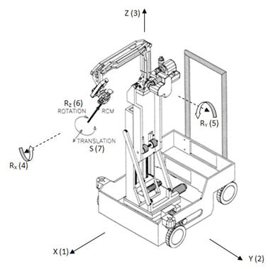
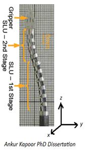
The first task in controlling the robot is to find the combined forward kinematics map. In the previous studies, detailed kinematic analysis of both systems are employed. In this project what needs to be done is to develop a method to combine both forward kinematic equations. In doing this I carried all the snake frame equations into the LARS coordinate frame. The Snake and the LARS coordinate frames can be seen in the below Figures.

 Physically speaking, Snake Robot is to be mounted on the insertion (s(7)) axis of the LARS robot. A tricky point which must be taken into account is that the direction of z-axis of the LARS robot and the Snake robot. As can be seen the directions are reversed when the robot in Figure 5 is mounted upside down. So the existing Snake forward kinematic equation should be subject to this transformation for which case the 4×4 transformation matrix of the Snake forward kinematic matrices should be multiplied with the rotation rotated around x-axis by an amount of 180 degrees. Details of this analysis can be seen in the Final Report below.
* Control Overview
The system developed has 7+4=11 degrees of freedom. So the system is already kinematically redundant such that, for 3 translational and 3 rotational unknowns (x, y, z, Rx, Ry, Rz) there are 11 variables to be determined.
The LARSnake robot motion can be classified as:
In coarse motion, the snake will not move so the system will turn out to be 7 degrees of freedom LARS. So in implementing the constrained optimization algorithm, in developing the objection function matrix the coefficients of the snake actuators should be penalized more such that they should be larger.
In fine motion, it is aimed that x, y, z axis actuators will not move and the system will be an 8 dof system. In this motion RCM mode operation can also be developed as given as an example in the study [3].
In the optimization problem,|(|A∆q-b| )| is the objection function under the constraints C∆q-d≥0. As noted above the first critical part of the implementation process is the forming the objection “A and b” matrices. The first part of the “A” matrix will be made of the combined Jacobian of the system under concern. Below this, the weights of each actuator will reside diagonally. Depending on the type of the motion described above the penalization constants will differ. Likewise, the first part of the “b” column vector will be 6×1 the desired position and orientation of the end effector. Below it there will be zero.
Now that the objection function is formed, the next job is the formation of the constraint matrices “C” and “d”. In snake side of the system, the constraints play a very important role because the capabilities of the snake robot are limited. It can bend around -40, +40 degrees from its equilibrium point so certain constrains are needed in order not converge to a value out of this range. In snake currently it is planned implemented:
Besides, in RCM mode certain constraints at the LARS side of the robot should be put. In doing that, the objection Jacobian should be changed such that the Jacobian should be recalculated at the RCM point. Again in this motion Cartesian axis actuators of the LARS side should be penalized more in order the keep that RCM point at a fixed location in space.
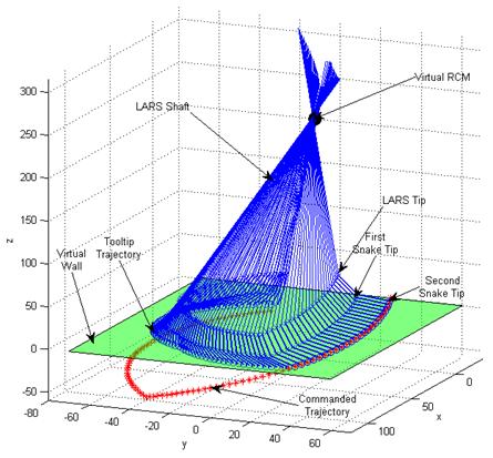
In addition to the RCM mode of operation, a simulation of the Virtual wall is also implemented in this study. As described in [4], a virtual RCM can be implemented on the robot as follows. Assume, for now, that the tool shaft is passing through the virtual RCM (point X0) at the current time step. The robot task then would be to maintain that point on the axis of the tool shaft, i.e. movements of that point in the directions perpendicular to the shaft should be restricted to a small value ε . This way we are restricting that point to move inside a virtual cylinder around the tool shaft. This problem, in its original form, is nonlinear since it involves finding the distance from X0 at the next time step to the fixed virtual RCM
In addition to the RCM mode of operation, a simulation of the Virtual wall is also implemented in this study. As described in [4], a virtual RCM can be implemented on the robot as follows. Assume, for now, that the tool shaft is passing through the virtual RCM (point X0) at the current time step. The robot task then would be to maintain that point on the axis of the tool shaft, i.e. movements of that point in the directions perpendicular to the shaft should be restricted to a small value ε . This way we are restricting that point to move inside a virtual cylinder around the tool shaft. This problem, in its original form, is nonlinear since it involves finding the distance from X0 at the next time step to the fixed virtual RCM
The result of the optimized control with both the virtual wall and virtual RCM constraints can be seen in the below Figure.

[1] J. Funda, R. Taylor, B. Eldridge, S. Gomory, and K. Gruben, “Constrained Cartesian motion control for tele-operated surgical robots,” IEEE Transactions on Robotics and Automation, vol. 12, pp. 453-466, 1996 “pdf”
[2] A. Kapoor, M. Li, and R. Taylor. Constrained Control for Surgical Assistant Robots. IEEE Int’l Conf. on Robotics and Automation. pp. 231-236. May 2006. “pdf”
[3] A. Kapoor. Motion Constrained Control of Robots for Dexterous Surgical Tasks. Johns Hopkins University Ph.D. Thesis. Sept, 2007 “pdf”
[4] Additional readings on Seth Billings and Ehsan Basafa CIS 2 project proposal report on “ Teleoperation of LARS Robot”