Contact Us
CiiS Lab
Johns Hopkins University
112 Hackerman Hall
3400 N. Charles Street
Baltimore, MD 21218
Directions
Lab Director
Russell Taylor
127 Hackerman Hall
rht@jhu.edu

Last updated: 6/05/2013 16:09pm
The most common treatment for hydrocephalus is to place a cerebrospinal fluid (CSF) shunt to divert excess CSF to a re-absorbtion site and regulate the intracranial pressure. However, CSF shunts have an unacceptably high incidence of occlusions from in-grown tissues. Our project is to explore ultrasound imaging, together with photoelectric excitation to image the occlusions and brain shunts, so a system of minimally invasive clearing of the brain shunts could be further developed.
The following pictures demonstrate brain shunts and the method under development to clear the occlusion in the brain shunts.


(Version 1)
Clinical Background
Hydrocephalus is caused by excessive cerebrospinal fluid (CSF) accumulates in the ventricular space, creating increased pressure on the brain. Pressure distends ventricles and can lead to death. The most common treatment for hydrocephalus is to place a cerebrospinal fluid (CSF) shunt to divert excess CSF to a re-absorbtion site and regulate the intracranial pressure.
Neurosurgeons place shunts by making scalp incision and drilling hole in the skull, then passing a small catheter (1.5mm inner dia.) through the brain into a ventricle (often 3rd ventricle). the distal catheter is placed under skin to peritoneum. 40,000 shunt-related operations are performed annually in US.
However, CSF shunts have an unacceptably high incidence of occlusions from in-grown tissues like choroid plexus, connective tissue, neurogliosis and blood, that block CSF flow. Failure rates are estimated to be ~40% in the first year and ~80% within 10 years. Currently, the only accepted clinical solution for resolving obstructions is either shunt replacement or revision. If removal of malfunctioning shunt presents hemorrhage risk, the shunt is left and new shunt placed.
Technical Background
Photoacoustic imaging, which is based on the photoacoustic effect, possessing many attractive characteristics such as the use of nonionizing electromagnetic waves, good resolution and contrast, portable instrumention, and the ability to partially quantitate the signa, has developed extensively over the last decade. It was first discovered by Alexander Graham Bell in 1880. Electromagnetic (light) waves are converted to acoustic waves due to absorption and thermal excitation.The photoacoustic effect has been previously exploited to lead to the invention of photoacoustic spectroscopy and is currently used in biomedical applications such as structural imaging, functional imaging, and molecular imaging.
By lauching high frequency pulses of light onto a medium, the energy of the light is absorbed and converted into heat, which makes the molecules become thermally excited. Then the pressure variations caused by radiation of the heat will propagate as ultrasound waves in the medium. So it can be detected by acoustic devices such as ultrasound.
(Version 1)
(Version 3)
<fs large>Proposed Solution</fs>
In order to conquer this weakness that ultrasound cannot penetrate skull, photoacoustic imaging technique is used. To generate photoacoustic effect, laser system is integrated with the ultrasound system.
Working Principle Specification:
A high frequency pulses of light is launched onto the occlusion. The energy of the light absorbed by the occlusion will convert into heat, which makes the molecules become thermally excited. Then, the pressure variations caused by radiation of the heat will propagate as ultrasound waves in the occlusion. So that it can be detected by ultrasound probe.

<fs large>Feasibility Demonstration of The Proposed Solution</fs>
<fs larger>Phantom Construction</fs>
This project is to develop a new technology that can be used for the Ventricular Brain Shunts. A phantom, that can mimic the ultrasound properties of human brain, needs to be prepared for the investigation.
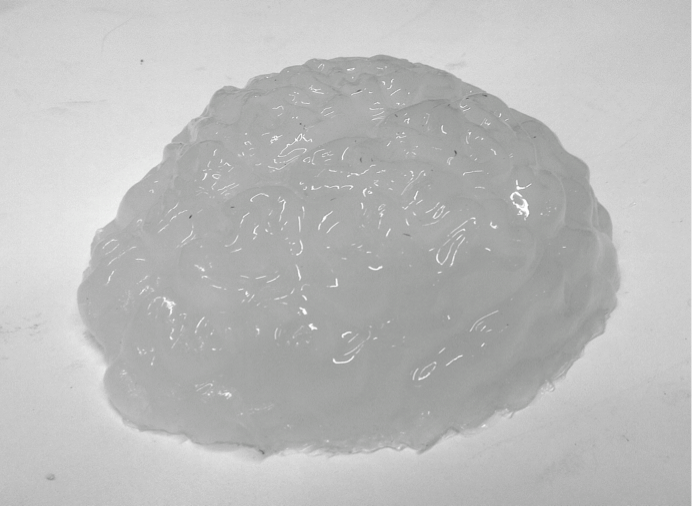
For the brain part, we choose the polyvinyl alcohol cryogel (PVA-C) as the main building material. PVA-C is a typical tissue-mimicking material for ultrasound imaging. It is formed from PVA solution undergoing some freeze-thaw (F/T) cycles. As the optical and mechanical properties change with the number of F/T cycle, certain requirements, like the scattering coefficient and absorption coefficient, for the phantom can be achieved. This kind of phantom can be used in a permanent way under humidity-controlled conditions.
The construction process is specified below:
Step 1. to 4. is a whole F/T cycle. If needed, this F/T cycle can be repeated for several times. Without the addition of dimethyl sufoxide, the scattering coefficient will increase with each cycle and the phantom will be stiffer, too. The figure below is one of the phantoms we created.
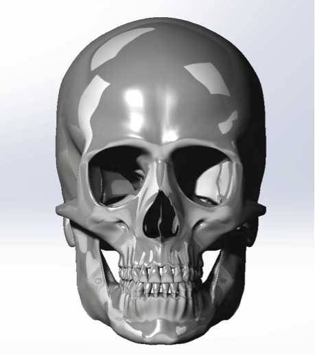
For the skull part, we proposed a construction process here. But we finally choose to use fresh bones for the experiment because the unavailability of the specific type 3D printer.
The typical construction process for medical model is specified blew:
In step 6., the infiltration is performed by immersion under vacuum conditions in a dedicated chamber. The samples were maintained at -95kPa for min, at the temperature of 25°C. Then, the atmospheric inlet valve is opened to relieve the vacuum, causing a further penetration of the infiltrant by atmospheric pressure action. Finally, the samples are extracted from the chamber and the excess resin is wiped off the surface.
The image below is the snotshot of the 3D Model we created in the Solidworks.
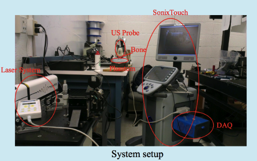
<fs larger>System Setup</fs>
The Photoaoustic Laser System of OPOTEK Inc. has been used to project pulses at 1064nm wavelength into a fiber of 1mm diameter, which has been inserted into the shunts with its tip directly pointing to the occlusion material. SonixTouch ultrasound system, developed by Ultrasonix Medical Corporation (Richmond, Canada), was used to detect the excited acoustic waves, together with a transducer probe placed right on top of the phantom. The Sonix DAQ device, jointly developed by the University of Hong Kong and Ultrasonix, was used to collect the pre-beamformed radiofrequency (RF) data from the US machine into .daq files. Finally, those .daq files are processed with MATLAB to get the beamformed image.
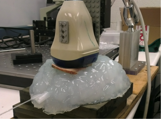
<fs larger>Experimental Setup</fs>
A shunts mimicking plastic tube containing water and occlusion has been inserted into the brain phantom horizontally. The transducer probe has been put in aligned with the shunt. Figure 7 shows a B-mode ultrasound image of the shunts inside the phantom, with fiber and occlusion inserted. Though we cannot see the fiber and the occlusion in the shunts clearly, their positions can be decided by the shadows they have created below them.
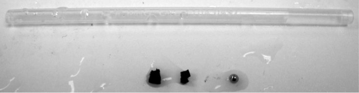
High attenuation jello-based material has been used to mimic the occlusion. Nova of Ophir Optronics has been used as the laser energy/power meter. Energy between 0.7mJ/cm2 to 1.5mJ/cm2 at the fiber end tip has been adopted for the experiments, which is much lower than the maximum allowable energy of 30mJ/cm2 exposed on tissue according to the ISO laser safety standards. A limitation of our occlusion material is that it will get burnt when the laser energy is over 1mJ/cm2, and no signal will be generated after that. A brachytherapy seed has been put right before the occlusion material to prevent this situation when high energy is needed in the experiments of visualization of the fiber end point. The occlusion at the end of the shunt is used to prevent water from leaking out, which is far out of the FOV.
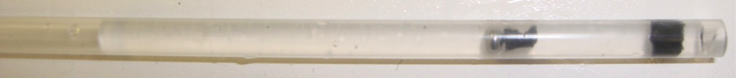
Different sizes of the occlusion material have been prepared for imaging in Figure.. The thickness is halved for the second occlusion.
To mimic human skull, a fresh pig pelvis bone has been cut and shaved into two pieces of different thickness, 2mm and 4mm. Then, one of the two pieces has been inserted between the phantom and the transducer probe.
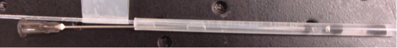
In the experiments to visualize fiber end point, a metal needle has been tied up together with the fiber, and a piece of occlusion material has been put at the end of the needle. The acoustic wave generated by the seed and the occlusion will be reflected by that piece of occlusion material, so the position of the fiber end point can be seen in PA images.
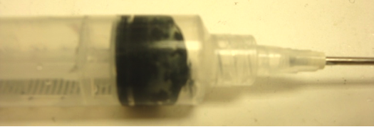
To mimic the reversed process of clearing the shunts, occlusion material has been cut into tiny pieces and mixed with ultrasound jell to put into a injection syringe and inject into the shunts. Therefore, visualization of the accumulation of the occlusion could be achieved.
(Version 3)
Dependency: Access to Dr. Boctor’s lab and equipment
Dependency: Get the brain phantoms
Dependency: Learning how to collect the data using external probe
Dependency: Learn how to connect new software to the device
Dependency: Monitor the delayed clearing procedure of brain shunts
(Version 2)
(Version 3)
[1]. Sean Jy-Shyang Chen, Pierre Hellier, Jean-Yvs Gauvrit, Maud Marchal, Xavier Morandi, and D. Louis Collins, An Anthropomorphic Polyvinyl Alcohol Triple Modality Brain Phantom based on Colin27, Mechanical Image Computer-Assisted Intervention – MICCAI 2010 6362 (2010) 92-100.
[2]. Fre ́ de ́ ric Bevilacqua, Dominique Piguet, Pierre Marquet, Jeffrey D. Gross, Bruce J. Tromberg, and Christian Depeursinge: In vivo local determination of tissue optical properties: applications to human brain. 1 August 1999/ Vol.38, No.22/ Applied Optics.
[3]. Matteo Gatto, Gianluca Memoli, Adam Shaw, Neelaksh Sadhooo, Pierre Gelat, Russell A. Harris, Three-Dimensional Prinrting (3DP) of neonatal head phantom for ultrasound: Thermocouple embedding and simulation of bone, Medical Engineering &Physics 34 (2012) 929-937.
[4]. Limng Nie, Xin Cai, Konstantin Maslov, Alejandro Garcia-Uribe, Mark A. Anastasio, Lihong V. Wang, “Photoacoustic tomography through a whole adult human skull with a photon recycler”, Washington University, Department of Biomedical Engineering, St. Louis, Missouri 63130.
[5]. H. J. Kang et al., “Software framework of a real-time pre-beam-formed RF data acquisition of an ultrasound research scanner,” Proc. SPIE 8320, 83201F (2012).
[6]. N. Kuo, H.J. Kang, D.Y. Song, J.U. Kang, E.M. Boctor, “Real-time Photoacoustic Imaging of Prostate Brachytherapy Seeds Using a Clinical Ultrasound System”, Journal of Biomedical Optics, 17(6), June 2012.
[7]. P. J. Stolka, H.-J. Kang, and M. B. Emad, “The MUSiiC toolkit: Modular Real-Time Toolkit for Advanced Ultrasound Research,” MIDAS Journal, (2010)
[8]. H.-J. Kang, P. J. Stolka, and M.B.Emad, “OpenITGLinkMUSiiC toolkit: A Standard Communications Protocol for Advanced Ultrasound Research,” MIDAS Journal, (2010)
[9]. M. Fink, “Time reversal of ultrasonic fields-Part I: Basic principles”. IEEE Trans. Sonics Ultrason. 39(5), 555–566 (1992).
[10]. J.-L. Robert, M. Burcher, C. Cohen-Bacrie, and M.Fink, “Time reversal operator decomposition with focused transmission and robustness to speckle noise: Application to microcalcification detection”. J. Acoust. Soc. Am., 119:3848-3859 (2006).
* Project MATLAB beamforming code