Robone: Next generation robot for orthopaedic surgery
Last updated: May 11, 2015 at 3 PM
Summary
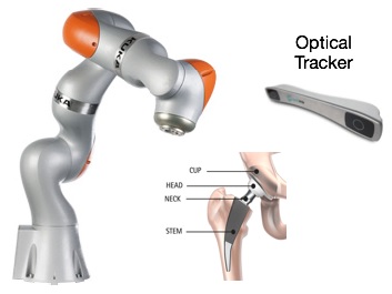
Hip replacement, one of the most common orthopaedic operations, is a surgical procedure in which the hip joint is replaced by a prosthetic implant. This joint replacement orthopaedic surgery is conducted in some hip fractures and generally helps relieve arthritis pain. Surgical devices have been developed in the past few years to help the surgeon conduct a more precise and time-efficient surgery. Although these devices have proven to be helpful, they can be invasive and need the patient to be fixed to the table for accuracy. With this regard, a new generation orthopaedic device with real time position adjusting capabilities could result in less invasive surgeries as slight position changes can be compensated by the system. Our goal in this project is to develop such a device utilizing a serial manipulator and an optical tracker.


Mentor(s):
Prof. Kazanzides
Prof. Taylor
Background, Specific Aims, and Significance
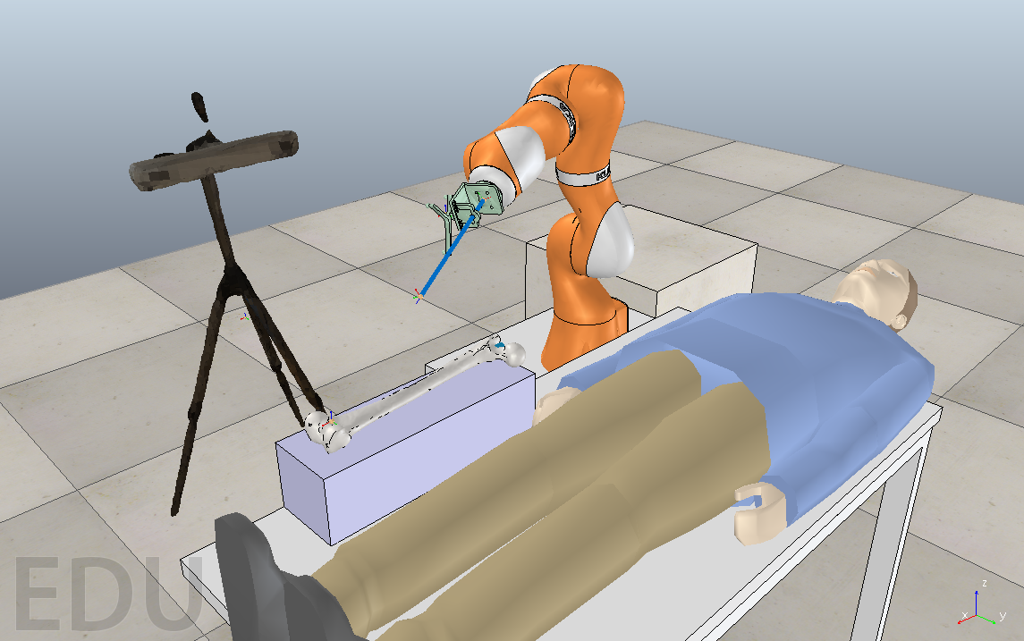
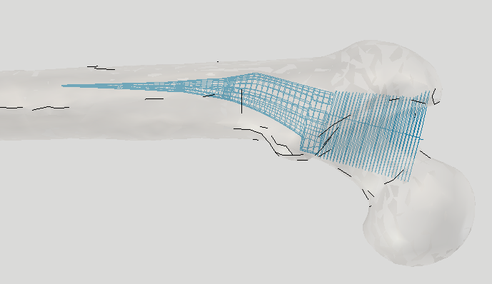
The existing computer assisted orthopedic surgical devices for hip replacement surgery are not perfect and require the patient to be fixed to the operating table, an invasive and time consuming process. A next generation system will make real time position adjustments using a device such as an optical tracker so fixation is no longer necessary. The goal is to enable faster and less invasive surgery with this type of computer assisted tool. First step is to read the arm state and make the end effector of the arm follow the desired cut path (cutting the shape of the implant on the bone). Then utilizing a device such as an optical tracker, real time position of the bone is obtained and the end effector path is adjusted in accordance with this position data. Final attempt would be integrating a milling device to the end effector of the arm and cutting the shape of the implant on a bone-shaped object or simply any object to test the precision and feasibility of the device.
Deliverables
Technical Approach
Below we outline the technical approach we will take to completing our project.
Outline of Software Design
Initial Software Design Concept
The initial software design is to integrate existing tools to create a first working prototype. Then, if those first pass implementations don’t meet our requirements, we can improve or replace components as needed. Design, implementation, evaluation, testing and iteration of these components will be done using the scrum process management method, which is described later in this document.

Updated Software Design
We developed a C++ motion control software stack to control the movement of the KUKA LBR iiwa robot. The V-REP simulation suite calculates the robot’s next target position and our software commands the motion of the robot end effector. The motion controller can also monitor the real time information of the joint angles of the robot. The updated and final software design is illustrated in flowchart below.

Outline of Project Plan
There are also some items of note to put this outline into context. The time in brackets [1] is measured in Ideal Full Time Equivalent (FTE) days. The names are of the people who will take leadership roles on those tasks, others may contribute substantially. Also, the scrum method allows reallocation of tasks, including the time, order and leadership roles during sprint planning. Finally, each level of deliverables (min, expected, and max) includes all previous ones.
Team startup
Complete
Introduce software tools [0.5][Andrew, Alex, Shahriar]
Introduce programming and controlling kuka arm [0.5][Andrew, Alex, Shahriar]
Introduce simulation software, V-REP [0.5][Andrew, Alex, Shahriar]
Create shared repository for software development [1][Andrew]
Evaluate additional methods to measure accuracy of results [1][Andrew, Alex, Shahriar]
Initial Simulation
Complete
Create a simulation of the system in V-REP without optical tracker
Add arm to simulation [1][Andrew]
Integrate motion planning
Add milling simulation of simple object [2][Shahriar]
Milling simulation of bone shaped object [2][Alex]
Add simulation with optical tracker [5][Andrew, Alex]
Initial Arm Integration - min deliverable
Complete
Implement basic Java setup on Sunrise Connectivity suite [2][Alex]
Implement and test read arm state over Fast Robot Interface (FRI) [3][Andrew]
Implement and test commanding arm motion over FRI [2][Andrew]
Collaborate with other kuka groups, if possible on path planning [3][Andrew, Alex, Shahriar]
Move along simple series of points (joint and/or cartesian space) [5][Andrew, Shahriar]
Cut file integration - min deliverable
Complete
Acquire ascii cut files [0.5][Andrew]
Implement ascii parsing and conversion to format amenable to sending to planner or arm as commands [4][Alex]
Test parsing and motion commands in simulation [2][Shahriar]
Test parsing and motion commands on physical robot [2][Shahriar]
Optical tracker integration - expected deliverable
Complete
Estimate bounds of acceptable system response time with respect to bone motion [2][Alex]
Acquire optical tracker [0.5][Andrew]
Setup of optical tracker with kuka [1][Andrew]
Implement reading of optical tracker data into software, using existing saw components [3][Alex]
Integrate optical tracking data into cut file and arm commanding loops [5][Andrew]
Reaction time testing [5][Alex]
Draw a straight line on an object, move object and check response time
See “physical simulation of cutting” idea below
Characterize response time
Improve response time if necessary
Simple redundancy checking of arm base and end effector position against optical tracker for consistency, safety, and reliability [3][Shahriar]
Make sure the motion of the robot is consistent with the motion of the optical tracker [2][Shahriar]
Trigger alarm if optical tracking system says that the robot is out of the planned motion [2][Shahriar]
Milling Physical simulation - max deliverable
Postponed
We will create a physical simulation of cutting, as opposed to a computer simulation.
The initial concept is to put an optical tracker fiducial on the end effector and have a clear box to simulate “bone”. We can then use the optical tracker to generate a simulated estimate of actual cutting. This avoids the complexity of acquiring materials to cut and dealing with the dust created by milling foam, wood or other test cutting materials.
Design and Create fiducial mounting attachment [5][Shahriar]
Implement logging of physical simulation [5][Andrew]
Integrate logging with V-REP to visualize execution
of simulation [5][Alex]
Implement method to evaluate planned vs actual path within error bounds of sensors [5][Andrew, Alex]
Create evaluation analysis [2][Shahriar]
Investigate arm motion planning - max deliverable
Postponed
Investigate and estimate other motion planning tasks more accurately [3][Andrew]
Minimize elbow movement during cutting scenario [13][Andrew]
Adjust cutting speed based on torque resistance of cutting [13][Shahriar]
Investigate response and pre planning to avoid going beyond joint configuration limits. Consider stopping in real time and asking user to move bone and arm to a new position within the workspace [13][Alex]
Response to human touch, stopping path, following human pressure, and then resuming motion when human moves it approximately back on path [13][Alex, Shahriar]
Milling integration - max deliverable
Postponed
Install physical milling equipment on arm and demonstrate real output shape cut from a demo material such as wood.
Create or acquire milling attachment (or whatever other mechanism we will use) [5-10][Shahriar, Andrew]
Investigate and estimate design and fabrication steps more accurately [3][Andrew, Shahriar]
Test milling attachment [3] [Shahriar, Andrew]
Integrate control of milling attachment with rest of system [5][Alex]
System testing and iteration
Postponed
Test complete system [3][Andrew, Alex, Shahriar]
Improve issues found [5][Andrew, Alex, Shahriar]
Dependencies
* KUKA robot arm - Serial manipulator
KUKA robot arm will be utilized to follow the cut path. If not met, development will be done using simulation rather than real arm.
If not available, we will ask various labs in LCSR that have an identical arm for time on their arm
February 1
Resolved
* Logistics - Access to mentors
* Optical Tracker - Atracsys optical tracking device
For real time position adjustments. Tracking the real time position changes of the bone will not be possible if not met.
If necessary, we will first utilize simulations to build out the software infrastructure then implement integration with another model of optical tracker such as a polaris tracker
February 27
Resolved
* Possibility of integration of the optical tracker with arm software and controller
Utilizing this optical tracker demands integration with the arm software. Tracking the real time position changes of the bone will not be possible if not met.
We will consider integrating another optical tracker using CISST
April 10
Resolved
* Software - Higher quality level integration of arm control software
* Milling device - Integration of milling device as an end effector for the arm
Needed for real cutting of the bone (or another object such as foam). Max deliverables depend on acquisition of the milling device.
Acquiring the milling device from the machine shop. If not met, we simply use an electric drill.
April 30
Not resolved yet
Milestones and Status
Milestone name: Initial Simulation
Planned Date: Feb 19
Expected Date: Feb 19
Status: Completed
Milestone name: Initial Arm Integration
Planned Date: Mar 5
Expected Date: Mar 25
Status: Completed
Milestone name: Cut file integration
Planned Date: Mar 19
Expected Date: Apr 20
Status: Completed
Milestone name: Optical tracker integration
Planned Date: Mar 19
Expected Date: Apr 30
Status: Completed
Milestone name: Milling Physical Simulation
Planned Date: Apr 2
Expected Date: Apr 2
Status: Postponed
Milestone name: Investigate arm motion planning
Planned Date: Apr 16
Expected Date: Apr 16
Status: Postponed
Milestone name: Milling integration
Planned Date: Apr 30
Expected Date: Apr 30
Status: Postponed
Milestone name: Additional system testing and iteration
Planned Date: May 7
Expected Date: May 7
Status: Postponed
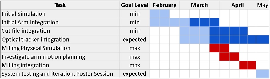
*Light Blue: Initial time frame
*Dark Blue: Updated time frame - Completed
*Red: Postponed for after the semester
Reports and presentations
Project Plan
Project Background Reading
Project Checkpoint
Paper Seminar Presentations
Project Final Presentation
Project Final Report
Project Bibliography
G. Boiadjiev, K. Delchev, T. Boiadjiev, K. Zagurski, R. Kastelov, V. Vitkov. Controlled Trust Force Influence on Automatic Bone Drilling Parameters in the Orthopedic Surgery. Int. J. of Pure and Applied Math. 2013; 88(4):577-592.
J. Pransky. ROBODOC ‐surgical robot success story. Industrial Robot. 1997; 24(3):231-233.
Taylor, Russell H., et al. Computer-integrated revision total hip replacement surgery: concept and preliminary results. Medical image analysis 3.3 (1999): 301-319.
Kazanzides, Peter, et al. Force sensing and control for a surgical robot. Robotics and Automation, 1992. Proceedings., 1992 IEEE International Conference on. IEEE, 1992.
Kazanzides, Peter, et al. An integrated system for cementless hip replacement. Engineering in Medicine and Biology Magazine, IEEE 14.3 (1995): 307-313.
Kazanzides P, Fichtinger G, Hager GD, Okamura AL, Whitcomb LL, Taylor RH. Surgical and Interventional Robotics - Core Concepts, Technology, and Design [Tutorial]. Robotics & Automation Magazine, IEEE 15.2 (2008): 122-130.
Albu-Schäffer, A., et al. The DLR lightweight robot: design and control concepts for robots in human environments. Industrial Robot: an international journal 34.5 (2007): 376-385.
Kroger, T. “Opening the door to new sensor-based robot applications—The Reflexxes Motion Libraries.” Robotics and Automation (ICRA), 2011 IEEE International Conference on. IEEE, 2011.
Kroger, T. “Online Trajectory Generation Algorithms as an Intermediate Layer between Robot Motion Planning and Control.” Workshop on Robot Motion Planning: Online, Reactive, and in Real-time. 2012 IEEE/RSJ International Conference on Intelligent Robots and Systems, IROS 2012
Taylor RH, Mittelstadt BD, Paul HA, Hanson W, Kazanzides P, Zuhars JF, et al. An Image-Directed Robotic System for Precise Orthopaedic Surgery. IEEE Trans on Robotics and Automation. 1994 Jun;10(3):261-275
Kazanzides P, Zuhars J, Mittelstadt B, Taylor RH. Force Sensing and Control for a Surgical Robot. In: IEEE Intl. Conf. on Robotics and Automation. Nice, France; 1992. p. 612-617
Zuhars J, Hsia TC. Nonhomogeneous material milling using a robot manipulator with force controlled velocity. In: IEEE Intl. Conf. on Robotics and Automation. Nagoya, Japan; 1995. p. 1461-1467
Stocco L. Path Verification for Unstructured Environments and Medical Applications. In: ASME Design Automation Conf., Symp. on Mechanisms and Devices for Medical Applications. Pittsburgh, PA; 2001. p. 1103-1108
Other Resources and Project Files
Here is the link to the repositories used for this project:
grl
Robone
Full source is available to people affiliated with JHU by contacting the developers.
Please contact Andrew Hundt for further information: ahundt at jhu dot edu


