Contact Us
CiiS Lab
Johns Hopkins University
112 Hackerman Hall
3400 N. Charles Street
Baltimore, MD 21218
Directions
Lab Director
Russell Taylor
127 Hackerman Hall
rht@jhu.edu

Last updated: April-7 at 14:00
Cranioplasty procedures are typically performed to remove tumors from the brain. As such, this process involves removing a section of the skull in order to access and resect the tumor. However, when concluding this type of procedure, the original skull fragment often cannot be used to fill up the defect. When initially removing the fragment, a large percentage of it turns into bone dust, rendering the fragment unusable. Currently, reconstructive surgeons, like Dr. Gordon, will modify a preoperatively designed implant by trial and error until the defect is covered. The new solution that Dr. Gordon, Dr. Armand, and Dr. Murphy are developing involves identifying the defect using a Polaris optical system and projecting that shape onto a 3D printed implant. The surgeon then tailors the implant to fit the skull using an outline traced using a projection system. While this process may be largely more accurate than the current trial and error procedure, there is significant room for improvement. This project will attempt to implement a handheld 3D scanning system that will reduce the cost and complexity of the projection enhanced modification system.


 Cranioplasties, also referred to as secondary cranial reconstructions, usually follow craniectomies administered in the case of severe trauma, stroke, or even brain tumors. The cranioplasty procedure is indicated for “cerebral protection, cosmetic appearance restoration, and treatment of the syndrome of the trephined.” For these reasons, the cranioplasty procedure is vital to the quality of life and health of patients. In many cases, however, the bone flap removed during a cranioectomy cannot be replaced for a variety of reasons, such as large gaps due to cutting, risk of infection, or even at the surgeon’s discretion. For these surgeries, the surgeon will generally use titanium mesh or an implant made of Poly-Methyl Methacrylate (PMMA) to fill the hole.
Recently, surgeons have begun to use Customized Cranial Implants (CCI) made of PMMA, which are fabricated preoperatively using Computer Assisted Design and CT scans of the patients head. The CT scans allow technicians to design an oversized implant over the region where surgery will be taking place. CCI’s provide many benefits to the patient, as well as the surgeon. As Dr. Gordon mentions in his paper, “CCI’s provide a full thickness calvarial reconstruction unlike titanium mesh, and may avoid unnecessary dead space underneath.” However, these sterile implants must be modified intraoperatively to obtain a perfect fit in the defect.
As seen in the current research being performed by Dr. Gordon, these cranioplasty procedures involving the intraoperative modification of a PMMA CCI can take almost an hour of surgical time. While the benefits of CCI’s negate the excessive amount of surgical time, this procedure has much room for improvement. In attempts to improve current procedure times, Dr. Gordon, Dr. Armand, and Ryan Murphy have created a system that implements the Polaris optical tracker and a laser projection system that can project a cut-line onto the CCI. This system is currently being tested, but shows promising initial results in decreasing overall operation time and helping the reconstructive surgeon make more precise first cuts. While minor modifications may still be required, the general guidance already helps significantly in reducing the amount of time spent by the surgeon for making modifications.
While the implementation of the Polaris system is already a huge step forward, there are some drawbacks to the current system. The Polaris optical tracking system, while highly accurate, is very expensive and difficult to set up. It also requires constant line of sight to the pointers, which can be difficult in a crowded operating room. The Polaris tracking system can also only measure points using a large rigid fixation on the skull of the patient and an unwieldy, optically tracked pointer. One major issue with this pointer based identification system is that it is difficult to collect points describing the various angles and shapes of the cranial defect. Currently, the point clouds that are obtained are quite two dimensional, lacking any information about the slanted sides of the defect.
With the advent of highly accurate, handheld 3D scanners, it is possible to create a system that is portable and that offers more information to the projection system and the surgeon. Using a tablet based scanner would provide a much cheaper and easier to use solution than the Polaris based defect identification process. This project proposes to develop the necessary algorithms and technological pipeline required for a 3D Scanner based system, which should simplify, as well as speed up, the cranioplasty procedure.
A proposed pipeline for the new implant modification process is shown below:
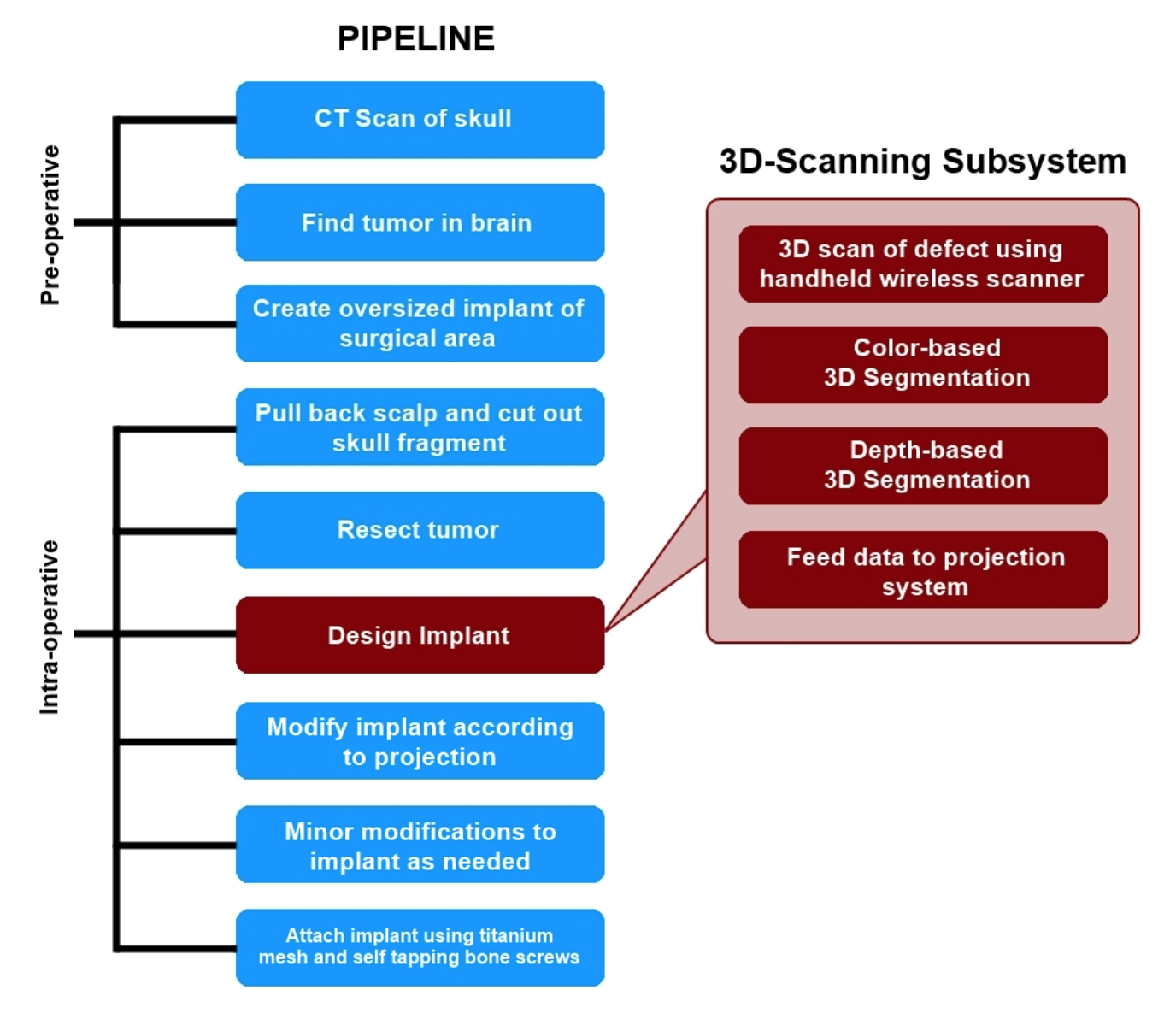
This project proposes to integrate a new subsystem into the cranioplasty pipeline for scanning the defect created during the procedure and the generation of a 3D mesh model that accurately describes the defect. First the surgeon acquires a preoperative CT scan of the patient’s head. Using this scan, the tumor is located and a customized cranial implant (CCI) is created. It should be noted that the CCI initially covers a greater area than the expected defect size. The implant will be shaped down to the proper size during the operation, using the new 3D-scanning enhanced subsystem as a guide.
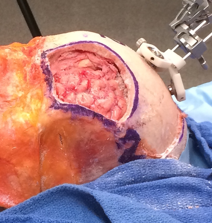
The surgeon begins the procedure normally by pulling back the scalp, marking the surgical area with a sterile surgical pen, and cutting out the skull fragment. Once the tumor is then removed from the brain, the cranial reconstruction process begins. With this new subsystem in place, the surgeon or nurse will use a handheld, wireless device to take a 3D scan of the defect. Note that for this project, we will be using an iPad mounted with a Structure Sensor as the “handheld scanner.” When scanning the defect with this device, the operator should hold the scanner within half a meter of the defect for the most precise measurements. Scanning should be done by pointing the sensor towards the defect at some arbitrary starting position, and then slowly moving it around the site until the scanner indicates the operator to stop. The built-in software for this scanner is very responsive in that it will notify the user to slow down, back up, or move to a previous location when needed.
Once the scanning is complete, the data is wirelessly uplinked to a computer where final rendering and colorizing takes place. Once a final mesh has been created, the program will begin attempting to identify the general region of the defect using a color-based segmentation. The segmentation algorithm will focus on markings around the surgical area made with the sterile surgical pen. This thick outline remains around the defect even after removal of the skull fragment, since the cut is smaller than the marked area. The results of this segmentation algorithm will be used to trim the 3D mesh file down to just the defect. The program then runs a depth-based segmentation algorithm that will calculate the depth and angle of the edge cuts. This is crucial information for the surgeon to have so he is able to make an accurate cut of the CCI. If this initial cut is more accurate, overall surgical time will be reduced by decreasing the time taken thereafter to make additional adjustments to the implant. A more accurate initial cut will also reduce the likelihood of gaps between the implant and the skull. Once the segmentation is complete, the mesh is then sent to a laser projection system. The image of a cut is overlaid onto the CCI, allowing the surgeon to cut the implant down to the proper size and fit. Once the initial cuts are made, the surgeon can try the implant on the defect and make minor modifications as needed. Finally, the implant is secured onto the defect with titanium mesh and self tapping bone screws.
We took a number of different approaches when trying to tackle this problem of extracting the inner wall from the mesh.
In our first few methods, our main tool of identify the triangles that made up the inner wall was the angle created between the normal vectors of neighboring triangles.
For every point on the mesh, we find the normal vector of all the triangles that include the point. Then, we compare each of those triangles to one another by determining the angle between the two normal vectors, and then take the average of all those angles. If the average was above a certain threshold, we included it, along with all the triangles that includes that point, into the output mesh file.
There were a bunch of different variations of this method that we tried, but all the results were pretty much the same: it got a good chunk of the inner wall (anywhere from 40 - 70% of it), but it also included a lot of unwanted artifacts.
Ground Truth:


Test Scan with structure sensor:

Ground Truth:


Test Scan with structure sensor:

Our results from the method above were not bad; we could have easily just used those results and just manually remove artifacts and fill the wall, and this would still have been faster than the current methods being used. However, we wanted to expedite the process as much as possible and with as little manual “fiddling” as possible. So, after thinking about it for a while, we came up with a new method, one which gives strikingly good results. This very well could be our final algorithm that we use (we still have to do a bit more testing to be sure this model is reusable).
There are two main distinctions between this method and our previous methods: 1) we give normal vectors to the points rather than on the triangles, 2) we compare angles between the normal of the points and the normal of the centroid rather than between neighboring normal vectors. Just with these two changes, we got a much more filled wall (60 - 80%) but were still getting a lot of artifacts.
To clarify, every vertex gets a normal vector, which is calculated by averaging the normal vectors of the faces that connect to the vertex. As for the centroid, we use the faces directly below it to find the normal vector.
We then came up with essentially a scoring system to help identify if a point should be included or not. For every point, we check if the angle between its normal vector and the centroid normal vector is above a certain threshold. If it is, then also check its neighboring points to see if they meet a certain threshold as well (4 “ring of points” around the original point). Neighbors farther away that meet the threshold have a higher weight when determining if the original point should be included in the mesh, but also have a stricter threshold to meet.
This addition drastically improved our results. We consistently got 90+% of the wall with only a few artifacts.
Finally, to acquire the last 10% of the wall and remove all the artifacts, we came up with a directional filtering system. Essentially, we only want to include points that have normal vectors which point towards the centroid. So, we take all the points that passed through the scoring system and determined if their normals were pointing to the center. We do this by checking if the distance between the centroid and the point is smaller than the distance between the centroid and the endpoint of the point's normal vector.


Ground Truth:


Test Scan with structure sensor:


As you can see, there are absolutely no artifacts that remain, and we get the entire wall.
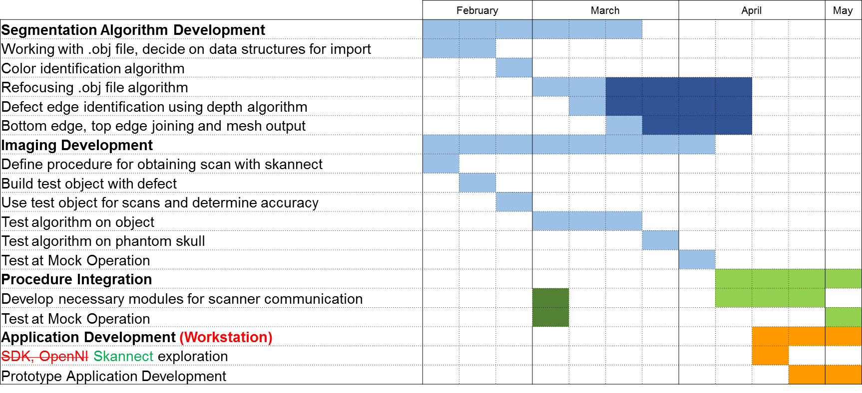
The following metrics will be used to determine the efficacy of the proposed pipeline:
* Structure Sensor - 3D scanning iPad accessory
* iPad - tablet for 3D scans
* Test Object - initial object to test scanner
* Phantom Skull - model of cranioplasty patient
* Mock Operations - Cadaver surgeries performed at JHMI