Contact Us
CiiS Lab
Johns Hopkins University
112 Hackerman Hall
3400 N. Charles Street
Baltimore, MD 21218
Directions
Lab Director
Russell Taylor
127 Hackerman Hall
rht@jhu.edu

Last updated: 5/4/16
The I-STAR lab is developing a dedicated cone-beam computed tomography (CBCT) scanner at Johns Hopkins University (JHU) for the detection and evaluation of intracranial hemorrhage. In the envisioned application, the scanner will be brought to the stroke patient and diagnosed at the point of care. Our project focuses on developing a digital simulator software and physical phantom in conjunction to aid in scanner characterization and validation of perfusion imaging techniques. We simulate the scanning process by first forward-projecting a digital head phantom enhanced by a simulated time attenuation curve following a gamma-variate function. By implementing a faster scaled forward projection, a 10-fold improvement in computational performance was observed, enabling testing of a number of relevant scanning parameters. To perform physiologically realistic perfusion imaging, a physical phantom was constructed to resemble blood flow in human brain capillaries. Together, the digital simulator and physical phantom form a general-purpose system for characterization and assessment of perfusion imaging solutions with CBCT scanners.
In the United States, acute stroke is the third leading cause of death. Responsible for approximately 1 in 15 deaths, stroke affects approximately 700,000 individuals in the US annually. There are two types of stroke. Ischemic stroke is a lack of blood flow to certain regions of the brain due to a blockage of a vessel while hemorrhagic stroke is either a brain aneurysm burst or a weakened blood vessel leak. Approximately 80% of stroke cases are ischemic in nature and the remaining 20% are hemorrhagic.The rapid and reliable visualization of blood flow in the brain at the point of care is critical for differentiating between ischemic and hemorrhagic stroke.
These different types of stroke are identified using conventional, unenhanced CT scans to locate regions of hemorrhage in the brain. Current approaches towards treatment of ischemic stroke in particular, frequently involves thrombolytic drugs designed to dissolve blood clots. However, use of these drugs is limited to a time window as the chance of hemorrhage increases with increased waiting time post stroke occurrence. Rapid data acquisition, diagnosis, and treatment are paramount factors in improving outcomes in these stroke cases.
One technique used to diagnose ischemic stroke includes a combination of CT angiography (CTA) and CT perfusion imaging (CTP). CTA focuses on the anatomical aspect of the diagnosis by targeting specific regions associated with vessel blockage. This technique is based on contrast-enhanced imaging to better visualize the blood vessel architecture. CTA requires an approximate steady state level of contrast during the image acquisition. On the other hand, CTP focuses on the physiological aspect of the diagnosis and aids in determining recoverable and irrecoverable regions of tissue. CTP tracks the motion of circulating iodinated contrast, known a contrast bolus as it moves through the vasculature.
 Fig 1. Time attenuation curve showing perfusion parameters
The underlying goal of CT perfusion imaging aims to identify regions in the brain which can be categorized to an ischemic core of critically irreversible tissue and into a penumbra, a region which is severely damaged but recoverable. Once the scan is performed, imaging software is used to generate a time attenuation curve (TAC) for each voxel in the image. Using these resulting TACs, perfusion parameters such as cerebral blood flow (CBF), cerebral blood volume (CBV), and mean transit time (MTT) are then calculated. Based on these parameters, physicians can localize the penumbra and ischemic core.
A dedicated CBCT scanner is currently being developed at Johns Hopkins University, specifically for the detection and evaluation of intracranial hemorrhage. Our project is concerned with the evaluating the feasibility of applying this scanner towards diagnosis of ischemic stroke in addition to hemorrhagic stroke. We are especially interested in the potential for brain perfusion imaging in expediting the diagnosis of ischemic stroke by performing the perfusion imaging at the point of care.
In order to validate a CT scanner for perfusion imaging, initial testing is necessary with a physiologically realistic brain phantom. A digital simulator is useful in understanding the optimal scanning parameters as well as the effects of various degrees of contrast enhancement. Our project aims to develop a digital and physical brain perfusion imaging phantom to test and evaluate the feasibility and performance of the CBCT scanner for characterization of perfusion parameters relevant to detection of ischemic stroke. In so doing, this digital simulator and physical phantom may be used as general platform to evaluate CT scanners for perfusion imaging.

Fig 2. Head Scanner developed by I-STAR Lab at JHMI
Dependencies for Digital Phantom:
Dependencies for Physical Phantom:
Advising Dependencies:
In order to thoroughly investigate the impact of the aforementioned parameters, we implemented a digital simulator of perfusion imaging. Due to the computational overhead of simulating a forward projected CBCT scan, we utilized CUDA tool software to enable parallel GPU processing. Figure XXXX shows a flow chart of our digital phantom. The inputs to our digital simulator include the following: head phantom image, selected regions of interest, time attenuation curve parameters, and scanner geometry inputs. The head phantom image is taken from [insert information]. The regions of interest (ROIs) can be selected based on a sphere defined by a radius and center or a manually identified set of voxels. These ROIs are presented as binary masks which may be optionally smoothed using a Gaussian kernel. The TAC input is defined as a gamma-variate function as shown in Fig. XXX. The parameters are maximum enhancement, delay time, time at which the maximum occurs, and an alpha parameter defining the shape of the curve defined in equation 1. Inputs can also be defined for the scanner which include detector size, source to axis distance (SAD), source to detector distance (SDD), frame rate, sweep angle, and scan speed. The method of rotation may also be defined to be a continuous unidirectional rotation or a bidirectional partial sweep.
There are two forward projection methods which were considered: brute force and faster scaling. The brute force method enhances a selected ROI in the head phantom image by a value determined by the TAC. This 3D matrix is then transferred to the GPU to perform separable footprint forward projection. Despite the efficient hardware implementation, this process must be repeated for each time point and thus poses a computational challenge. Due to these limitations, we propose a faster scaling method which significantly improves performance. In this method, the head phantom and the ROIs separately undergo a static forward projection. The ROI projection data is then enhanced by a value determined by the TAC and added to the head phantom projection data. This method works due to the linearity of the line integral operator as the enhancement value may be factored out of the integral. Instead of forward projecting at each time point, this method only requires a projection for the head phantom and for each ROI. Therefore, the forward projected head phantom and ROI may be efficiently combined knowing only the enhancement scaling as shown in equation 1.
The forward projected data then becomes the input for the next step of filtered backprojection. We initially used full sweep reconstructions and transitioned to partial short reconstructions sweeping over 180 degrees + fan angle, ensuring that the Parker weights were well defined. Our analysis of our reconstruction included varying time scan for a fixed frame rate and sweep angle. We quantified the tradeoff between spatial and temporal resolution by fitting the reconstructed data points to a gamma variate function. The goodness of fit was evaluated by calculating root mean squared error (RMSE) between our curve fit and the original TAC.
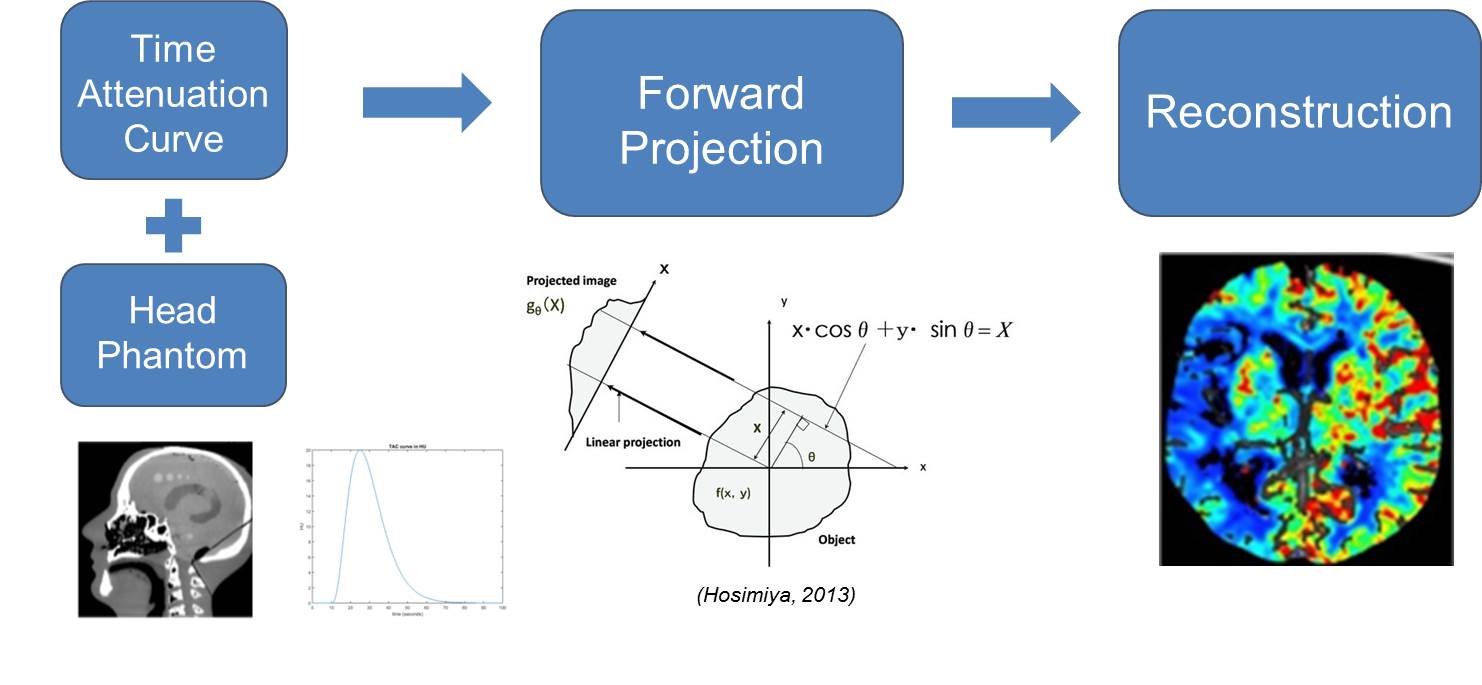 Fig 3. Technical Approach Overview
Figure XXX shows the output flow rate from our physical phantom setup with various pump settings. We see that the flow rate does not vary significantly with or without the perfusion chamber in the flow loop. This validates that our phantom is allowing fluid to pass through with minimal resistance for the peristaltic pump to overcome.
A comparison of the computational costs of our two forward projections models is shown in XXX. Our faster scaling method is able to achieve about a 10-fold increase in computational speed. We validated that our forward projection faithfully represented the TAC by plotting the middle line integral through the ROI for each projection and comparing it to the original TAC as shown in Fig XXX. These line integrals reproduced the same shape and location in time as the original TAC. Figure XXX shows our results of varying scan time in our filtered backprojection reconstruction. The results suggest a clear tradeoff between image quality and temporal sampling as the scan time was varied. A short scan time results in a high sampling of the TAC but poor image quality. Conversely, a long scan time results in sparser sampling but higher image quality. Figure XXX. suggests there may be an optimal scan time which minimizes the RMSE.
While the digital phantom is capable of simulating a wide range of theoretical results, a physical phantom is necessary to quantify variability associated with data collection. In order to accurately assess perfusion parameters with the CBCT scanner, the physical phantom seeks to model the neurovasculature found in the human body. We performed a literature search for existing phantoms. Among the several phantoms surveyed, we chose to base our design on the approach proposed by Wood et. al (2015), hereby referred to as the Wood phantom. Our decision was motivated by simplicity, reproducibility, quality of results, as well as physiological realism. This phantom has an overall cylindrical shape with 196 square channels of various diameter capillaries which made up the inside volume where flow occurred. The schematic from the Wood phantom design is shown in Figure X.
We also obtained the Masterflex L/S Economy Peristaltic Pump System, the Medrad Mark V Plus Contrast Injector and Omnipaque contrast agent to be used in our setup. We created a flow system which incorporated a contrast bolus from the injector with water cycled from the pump through a Y-shaped connector into our phantom and finally collected in a reservoir. Our setup is shown in Figure X.

Fig 4. Physical Phantom Setup
Our phantom was designed using SolidWorks and printed using the Stratasys Connex3 Objet 500 3D printer. We chose to make several modifications to the Wood phantom including barbed-tube fittings at the end of the cap, water-tight seal, and a modular design to vary the capillary diameter shown in Figure XX. The phantom was aligned along the XY direction of the printer with the channels of the phantom parallel to the build plate to ensure uniform sized holes. The printing time took approximately 2 hours and 15 minutes. To clean the support material from the channels followed a two step process. First we manually removed the support material using a high pressure water-jet and secondly used acupuncture needles to individually clean out each channel.
To characterize the achievable flow rates under different pump settings, we performed several validation experiments. These included running the pump at different settings both with and without the phantom. The flow rates were calculated by measuring the dispensed volume of water over a given time period. In each case, flow rates were computed by measuring the time required for the setup to pump 80 ml of water.
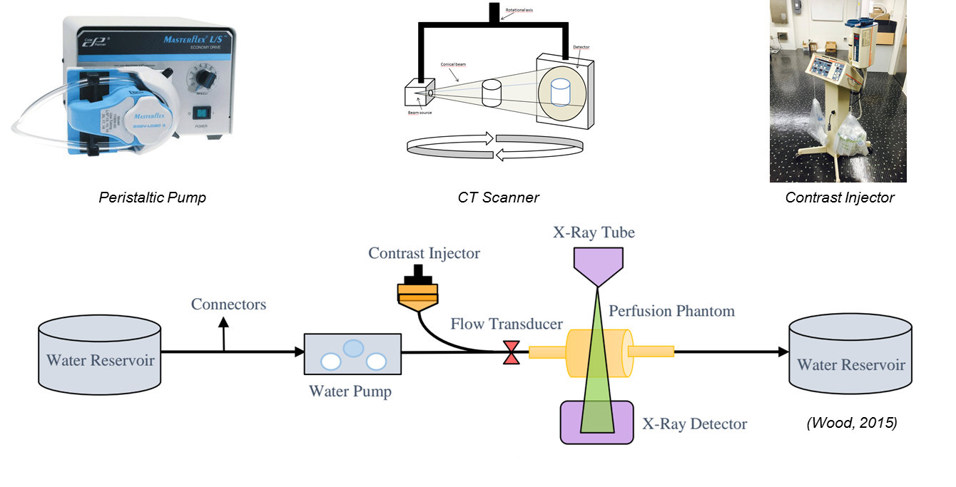
Fig 5. Wood Phantom Schematic
February 25: Submit proposal documents (Complete)
March 7: Complete forward projection for digital phantom (Complete)
March 12: Propose budget and begin ordering parts (Complete)
March 20: Finish CAD design (Minimum Deliverable Completed)
April 1: Complete reconstruction algorithm for digital phantom and finalize digital phantom
April 7: Complete initial prototype of physical phantom and begin testing (Expected Deliverable)
April 4: Finalize design of physical phantom
April 25: Complete testing and standardization of the physical phantom (Maximum Deliverable)
May 06: Final Presentation
April 25: Complete testing and standardization of the physical phantom (Maximum Deliverable)
May 06: Final report Presentation
Fig 6. Updated Timeline
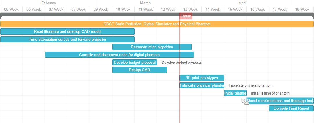
We were able to meet the aforementioned dependencies necessary for completing the project. We completed the entirety of our minimum and expected deliverable. However, since we spent a considerable amount of time to ensure a high quality digital phantom were unable to attain our maximum deliverable of testing the physical component.
As we have shown, our physical phantom is functional and capable of transitioning to scanning with the head scanner. As alluded to in this work, filtered backprojection has certain limitations in obtaining high image quality for shorter scan times. This idea strongly motivates the use of a model based iterative reconstruction method. Nevertheless, we have made significant progress in developing a physical phantom and digital simulator to be used in the validation of CT scanners for perfusion imaging applications.
We would like to thank the members of the ISTAR lab, especially our mentors Jeffrey Siewerdsen Ph.D., Wojciech Zbjiweski Ph.D., Nafi Aygun M.D., Alejandro Sisniega Ph.D., Russell Taylor Ph.D. We would also like to acknowledge the contributions of J. Webster Stayman Ph.D., Hao Dang, and Jennifer Xu.
Boese, A., Gugel, S., Serowy, S., Purmann, J., Rose, G., Beuing, O., … Deuerling-Zheng, Y. (2013). Performance evaluation of a C-Arm CT perfusion phantom. International Journal of Computer Assisted Radiology and Surgery, 8(5), 799–807. http://doi.org/10.1007/s11548-012-0804-4
Chiribiri, A., Schuster, A., Ishida, M., Hautvast, G., Zarinabad, N., Morton, G., … Nagel, E. (2013). Perfusion phantom: An efficient and reproducible method to simulate myocardial first-pass perfusion measurements with cardiovascular magnetic resonance. Magnetic Resonance in Medicine, 69(3), 698–707. http://doi.org/10.1002/mrm.24299
Driscoll, B., Keller, H., & Coolens, C. (2011). Development of a dynamic flow imaging phantom for dynamic contrast-enhanced CT. Medical Physics, 38(8), 4866. http://doi.org/10.1118/1.3615058
Ebrahimi, B., Swanson, S. D., Mosadegh, B., & Chupp, T. E. (2008). A Perfusion Phantom for Quantitative Medical Imaging. SPIE Digital Library, 6913, 69130W–69130W–8. http://doi.org/10.1117/12.770894
Fee, C., Nawada, S., & Dimartino, S. (2014). 3D printed porous media columns with fine control of column packing morphology. Journal of Chromatography A, 1333, 18–24. http://doi.org/10.1016/j.chroma.2014.01.043
Ganguly, a., Fieselmann, a., Boese, J., Rohkohl, C., Hornegger, J., & Fahrig, R. (2012). In vitro evaluation of the imaging accuracy of C-arm conebeam CT in cerebral perfusion imaging. Medical Physics, 39(11), 6652. http://doi.org/10.1118/1.4757910
Hindle, A. J., & Perkins, A. C. (1994). A perfusion phantom for the evaluation of ultrasound contrast agents. Ultrasound in Medicine and Biology, 20(3), 309–314. http://doi.org/10.1016/0301-5629(94)90071-X
Ionita, C. N., Mokin, M., Varble, N., Bednarek, D. R., Xiang, J., Snyder, K. V., … Rudin, S. (2014). Challenges and limitations of patient-specific vascular phantom fabrication using 3D Polyjet printing. Proceedings - Society of Photo-Optical Instrumentation Engineers, 9038(716), 90380M. http://doi.org/10.1117/12.2042266
Klotz, E., & Konig, M. (1999). Perfusion measurements of the brain: using dynamic CT for the quantitative assessment of cerebral ischemia in acute stroke. European Journal of Radiology, 30, 170–184. http://doi.org/10.1016/S0720-048X(99)00009-1
M, W. (2006). CT Perfusion of the Brain: The Basics of the method and interpreting images. Visions, 6–8.
Miles, K. A., & Griffiths, M. R. (2003). Perfusion CT: A worthwhile enhancement? British Journal of Radiology, 76(904), 220–231. http://doi.org/10.1259/bjr/13564625
Noguchi, T., Yoshiura, T., Hiwatashi, A., Togao, O., Yamashita, K., Kobayashi, K., … Honda, H. (2007). Quantitative perfusion imaging with pulsed arterial spin labeling: a phantom study. Magnetic Resonance in Medical Sciences : MRMS : An Official Journal of Japan Society of Magnetic Resonance in Medicine, 6(2), 91–97. http://doi.org/10.2463/mrms.6.91
R.G. Gonzalez, J.A. Hirsch, W.J. Koroshetz, M.H. Lev, P. Schaefer. (2006). Acute Ischemic Stroke: Imaging and Intervention Second Edition. Springer-Verlag
Wood, R. P., Khobragade, P., Ying, L., Snyder, K., Wack, D., Bednarek, D. R., … Ionita, C. N. (2015). Initial testing of a 3D printed perfusion phantom using digital subtraction angiography, 9417, 94170V. http://doi.org/10.1117/12.2081471