Contact Us
CiiS Lab
Johns Hopkins University
112 Hackerman Hall
3400 N. Charles Street
Baltimore, MD 21218
Directions
Lab Director
Russell Taylor
127 Hackerman Hall
rht@jhu.edu

Last updated: April 20, 12pm
The goal of this project is to develop a portable, 5 DOF laser cutting system. This robot-assisted system aims to help surgeons to quickly and accurately resize custom cranial implants (CCIs) in single-stage cranioplasty.
Cranioplasty is a procedure to treat and repair cranial defects using CCIs. The implants are usually made in oversized profiles, and require numerous iterations of manual modification to become suitable for patients. This process can take up to 80 minutes depending on the size of the implant and the complexity of the modification. Furthermore, the modification is based on the surgeon’s visual analysis, and therefore is prone to errors in precision and accuracy. The goal of our project is to enable faster and more accurate modification of the implant profile with robot-assisted technology.
Previous work related to our project is the computer-assisted technique using intraoperative navigation and projection to perform single-stage cranioplasty, in which regions of resected defects are detected using a digitizer to trace the outline of the defect on the skull. After the optical tracker captured all the points of the edge, the contour of the defect is projected onto the preoperatively-designed CCI for the surgeon to mark the desired shape and resize the implant manually. This technique provides a good closure fit with less gaps between the implant and remaining skull, and reduced the time needed for the manual modification.
Design requirement
The entire surgical procedure is to be performed under sterile environment. Therefore, the robot-based system is designed to cut the CCIs with laser instead of other methods (i.e. contact, stress, or pressure) in order to preserve sterility of the implant. The system is also designed to be compact so that the machine can be easily transported from one operation room to another. The CCIs are composed of biocompatible materials such as animal bone, autologous bone graft, acrylic resin known as bone cement (PMMA), or Polyether ether ketone (PEEK). It is important to note that different material requires different laser power setting. Preliminary test on a PMMA implant had shown a promising cutting effect with the laser system, so we will perform test trials on PMMA implants.
Technical Overview
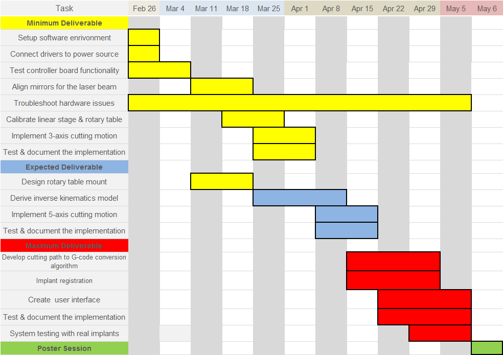
This project consists of eight steps (Figure 1).
1) surgical problem identification; 2) design approach of the laser cutting system; 3) CAD modeling and simulation of the system and hardware components; 4) fabrication and assembly of the hardware; 5) functionality testing and calibration of the hardware; 6) software development on motion controls and visualization; 7) system integration; 8) system assessment through experimental trials.
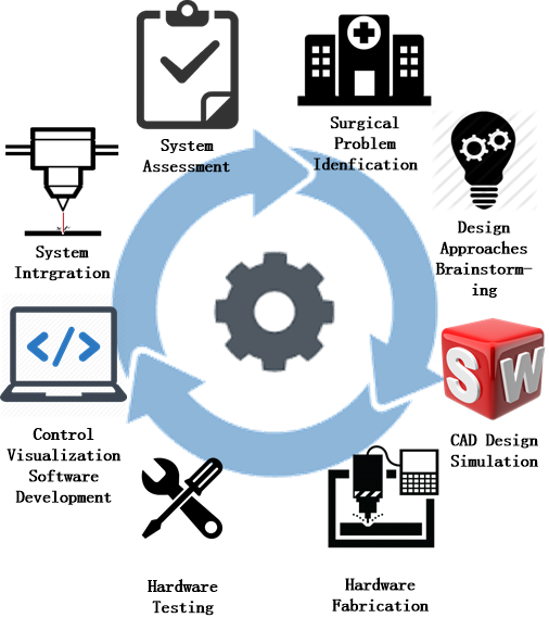
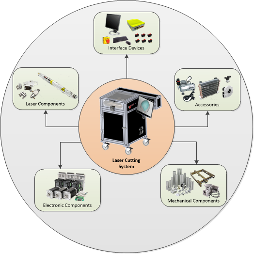
(Left. Fig.1: Project approach) (Right. Fig.2: System components)
System Overview
This robot-assisted laser system consists of five units: mechanical hardware, electronic components, laser components, interface devices, and accessories (Figure 2.) The system provides up to 5-axis of simultaneous motion to trim continuous edges on the implant with any desired angles. It is composed of three Cartesian linear stage (XYZ) and a rotary table (AB) with one nema series stepper motor. The stepper motor is controlled by its motor driver board, which in turn is controlled by a 5-axis breakout board (Figure 3). The laser source is a 35W CO2 sealed laser tube. Through three reflecting mirrors, the laser beam will be directed to shoot downward onto a rotary table, which is situated on top of a horizontal platform that controls the movement in the z-axis (Figure 4).
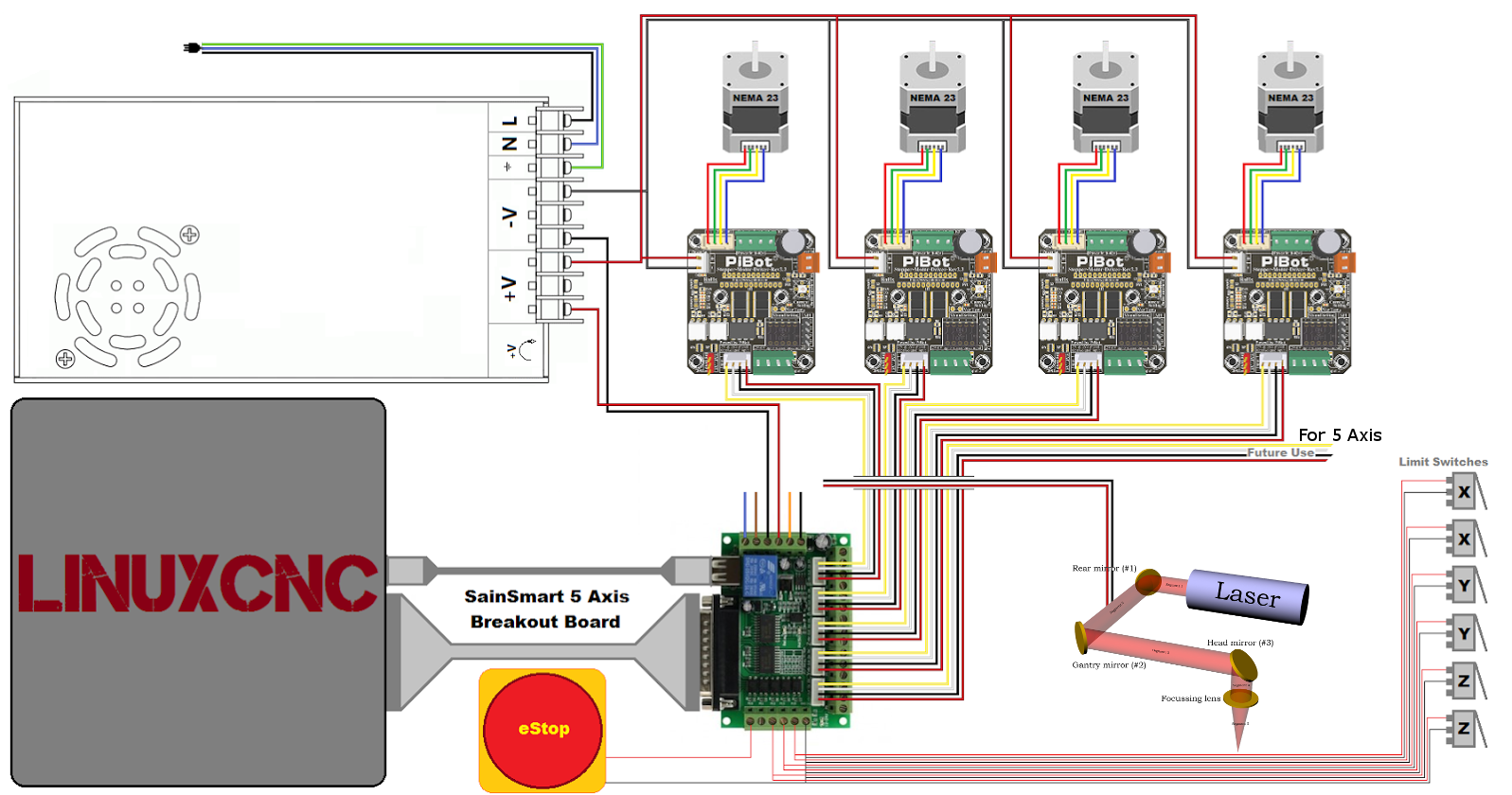
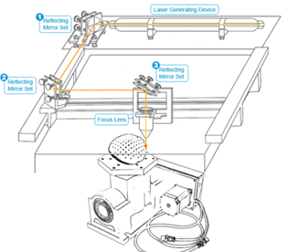
(Left. Fig.3: Electronic component) (Right. Fig.4: Configuration of linear stage & rotary table)
Software Overview
The software development of this laser cutting system falls under two categories: machine control and cutting path generation (Figure 5). For machine control, the existing version of LinuxCNC, which is an open source software that controls CNC machines, to operate the laser cutting system. This system reads the G-code and instructs the machine to move accordingly by sending control signals from NC-box to the controller board and eventually to drive the motors. In the preoperative interval, the system requires the calibration of the implant holder in order to minimize the time spent on implant registration during the surgery. In regard to the motion control of the machine, we will first develop a 3-axis control interface in LinuxCNC environment and further extend the development to a 5-axis control interface. For path generation, we will take the cranial defect model as the input to generate a cutting path. This cutting path will be converted to G-Code through our modified version of the open source software FreeCAD, and the G-Code will then be be executed by LinuxCNC.
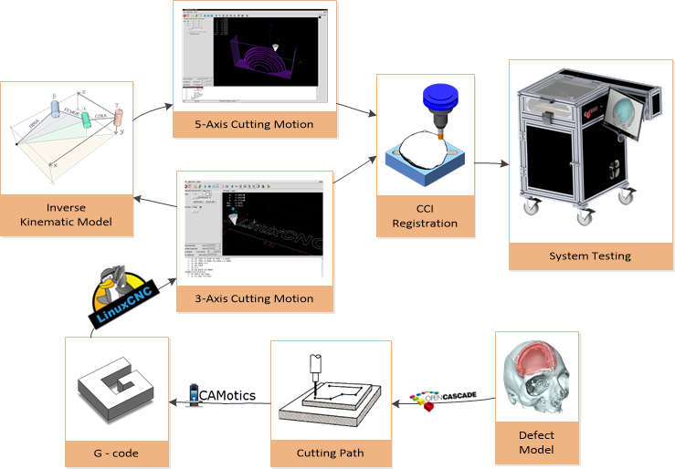
(Fig.5: Software development approach)
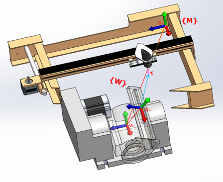
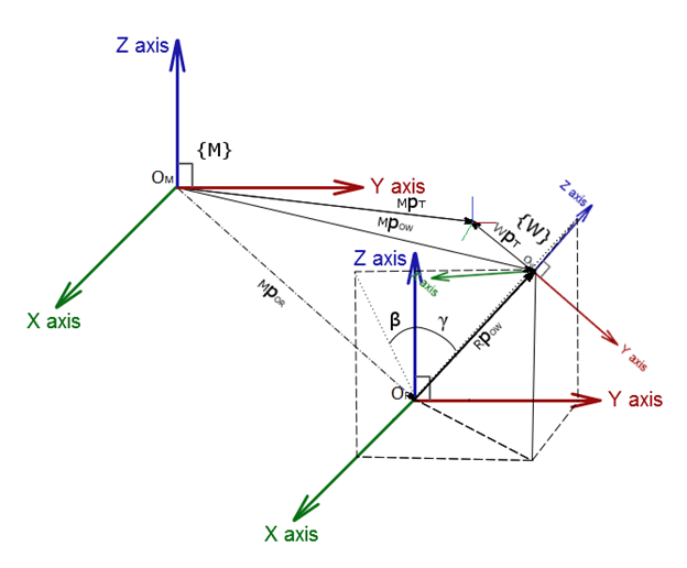
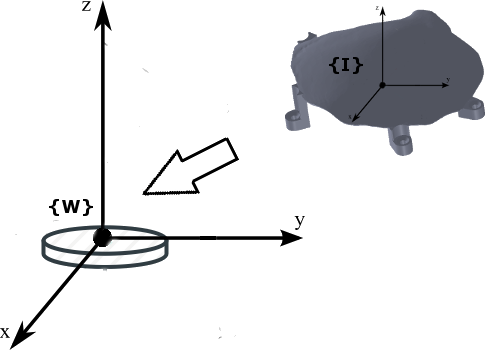
There are four frames to consider: the machine frame {M}, the workpiece frame {W}, rotary table intermediate frame {O}, and the tool frame {T}. The origin of {M}, {W}, and {T} is defined to be the home position of the system, the point on the mounting plate and above the point at which the two rotary axes coincide, and the tip of the laser head, respectively (see Figure 6). Because the implant is to be mounted on {W}, it is necessary to perform frame transformation from {M} to {W} (see Figure 7.). This is because for CAD/CAM system, a tool path defined by a set of successive tool positions and orientations (G-code) expressed in {W}.
 (Left. Fig.6 System frames)
(Right. Fig.7 Frame transformation)
(Left. Fig.6 System frames)
(Right. Fig.7 Frame transformation)
Forward kinematics
MPOR = [x0 y0 z0]T (translation from machine frame to rotary table -intermediate- frame)
tan(γ)= y/z (define angle)
tan(β)= x/z
L2=x2+y2+z2 (Distance at which the mounting plate is fixed by the length of the link L)
RPOW = [x y z]T = [L*tanβ/sqrt(tan2γ+tan2β+1) || L*tanA/sqrt(tan2γ+tan2β+1) || L/sqrt(tan2γ+tan2β+1)]T (position vector of the origin of {W} with respect to the rotary table)
MPOW=MPOR+MRR*RPOW, MRR = I (position vector of the origin of {W} with respect to {M})
A tool position is given by the position vector of the tool tip T in {W} as
WPT = [xt yt zt]T
and the tool orientation is given by unit vector associated to the tool axis direction as
WkT = [ktx kty ktz]T
The tool tip position vector and unit vector of tool axis direction in the frame {M} can be represented as
MPT= [xM yM zM]T = MPOW+MWR*WPT
MkT= [kTx kTy kTz]T = MWR*WkT
The position vector of {W} with respect to {M} can be defined as
MPOW = [xOW yOW zOW]T
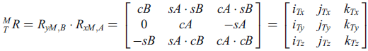
To bring {T} to a desirable angular position with respect to the {M}, {T} must be rotated first about the xM axis by an angle A, and then about the yM axis by an angle B. The rotation matrix MTR is as followed, where RyB and RxA are basic rotation matrices. Note: “c” is cosine and “s” is sine
Inverse kinematics
Using the above rotation matrix, the angles can be computed.
A = γ = atan2(-kTy,sqrt(1-kTy2) = atan2(sinγ,sqrt(1-sin2γ)
B = β = atan2(kTx/cosγ,kTz/cosγ)= atan2(cosγsinβ/cosγ,cosγcosβ/cosγ)
And the world coordinate (in {M}) can be represented as
x = [xM yM zM A B]T
Two contours are considered in creating the cut path: upper contour (P1) and lower contour (P2) (See Figure 8). The entire contour path is discretized into frames, and each frame contains one point from the upper contour and its corresponding point from the lower contour.
P1 = (x1 y1 z1)
P2 = (x2 y2 z2)
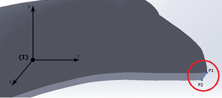
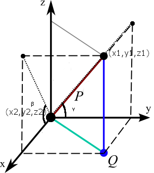
(Left. Fig. 8 Sample pair of points in {I})
(Right. Fig. 9 Angle calculation)
The angles can be calculated as followed
A = 90-γ = 90-atan2(∆z,∆y)
B = 90-β = 90-atan2(∆z,∆x)
There are two goals for the implant registration: Mapping the implant frame {I} to Workpiece frame {W}, and eliminating rotational offset (see Figure 10).
(Fig. 10 Frames of implant registration)
One approach taken into consideration is to use point cloud to point cloud rigid transformation.
1. Design a mount to secure implant on the work-piece
2. Drill two holes for screw placement as fixture
3. Register hole axes to the workspace {W}
4. Repeat step 2 on the implant
5. Register implant {I} to implant hole axes
This procedure requires the manufacture of the oversized implant to attach two screw holes on the implant, place a fiducial point on the implant surface, and provide us the coordinates of those three points. We will then control the linear stage to physically determine where those points are with respect to the machine frame {M}, which can then be transformed to {W}.
Path registration is used for point cloud to point cloud rigid transformation. It will map the contour of the cranial deformity to the implant frame {I}.
(Need to know the output format of the camera).
1. Hardware: this project involves the use of high power laser (class IV). We have completed the laser safety training. Status: resolved
[New] The current computer (NCbox189) does not have the necessary compiler to compile the kinematics model, and the system cannot be updated. We're currently using the lab computer and looking into a viable computer system to replace the current one. Status: pending
2. Software: we need the following software/library to assist us in this project. We have completed the installation. Status: resolved
3. Material: we need the data file of the raw implant material to complete the registration process. We will contact the cranioplasty surgeon, Dr. Gordon, for the materials. Status: resolved
4. Accessibility to laboratory: the laser cutting system is at the lab in Johns Hopkins Bayview Medical Center. We have acquired access to the lab. Status: resolved
5. Accessibility to machine shop: we need access to the machine shop to work on the design. We have completed the training and acquired access to all machines. Status: resolved
[1] R. J. Murphy, K. C. Wolfe, P. C. Liacouras, G. T. Grant, C. R. Gordon, and M. Armand.
Computer-assisted single-stage cranioplasty. 2015 37th Annual International Conference of the IEEE Engineering in Medicine and Biology Society (EMBC), 2015.
[2] Milutinovic, D., Glavonjic, M., Slavkovic, N., Dimic, Z., Zivanovic, S., Kokotovic, B., & Tanovic, L.. Reconfigurable
robotic machining system controlled and programmed in a machine tool manner. The International Journal of
Advanced Manufacturing Technology Int J Adv Manuf Technol, 53(9-12), 2010, pp. 1217-1229.
[3] D. Winder. Computer Assisted Cranioplasty. Virtual Prototyping & Bio Manufacturing in Medical
Applications, 2008, pp. 1-19.
[4] J. U. Berli, L. Thomaier, S. Zhong, J. Huang, A. Quinones-Hinojosa, M. Lim, J. Weingart, H. Brem,
and C. R. Gordon. Immediate Single-Stage Cranioplasty Following Calvarial Resection for Benign and Malignant Skull Neoplasms Using Customized Craniofacial Implants. Journal of Craniofacial Surgery, 26(5), 2015, pp. 1456-1462.
[5] R. Zavala-Yoé, R. Ramírez-Mendoza, J. Ruiz-García. Mechanical and Computational Design for
Control of a 6-PUS Parallel Robot-based Laser Cutting Machine. Advances in Military Technology, 10(1), 2015, pp. 31-46.
[6] P. J. Besl and N. D. McKay, “Method for registration of 3-d shapes,” in Robotics-DL tentative.
International Society for Optics and Photonics, 1992, pp. 586–606.
[7] R. J. Murphy, C. R. Gordon, E. Basafa, P. Liacouras, G. T. Grant, and M. Armand,
“Computer-assisted, le fort-based, face–jaw–teeth transplantation: a pilot study on system feasibility and translational assessment,” International journal of computer assisted radiology and surgery, 2014, pp. 1–10.
[8] Giorgia Willits, Shahriar Sefati, Russell Taylor, Mehran Armand, “Robotics Drilling for Single-Stage
Cranioplasty.” JHU Internal paper.
Video Demo
https://www.youtube.com/watch?v=6SbPwUWbtEM (System showcase)
https://www.youtube.com/watch?v=dzmyRiBEuD0 (5-axis demo video)
https://www.youtube.com/watch?v=qk8gIH5j1rg (5-axis cutting)
https://www.youtube.com/watch?v=xep14qN2xV8 (3-axis cutting)
https://www.youtube.com/watch?v=bmzivwM2UNU (motion testing)
https://www.youtube.com/watch?v=cdDJdmKOmFs (motion testing simulation)
https://www.youtube.com/watch?v=_7eQ9tD_Jf0 (Laser alignment)
Documentation
5-axis Cutting
Filename: laserkins.c
This is the kinematics file that used the above mathematical model to calculate forward and inverse kinematics. The file is written in C.
To use the file, compile the code in the terminal
(Steps)
Filename: 5-axis-cut-gcode
This file contains gcode that was written manually for the purpose of testing the system's ability to resize an implant.
Path Conversion
Filename: pathAngle.m
This is the algorithm that converts contour path to G-code. It calculates the angle between two points of the implant (one in the upper contour and the other in the lower contour) using the algorithm described in the “Cutting Path to G-Code” section. The input is two matrices containing coordinate of points in the upper and lower contour, respectively. The output is a (2n)x5 matrix containing coordinate of points [x y z A
B]. The second half of the matrix is identical to the first half in the sense that the laser system needs to loop through the path again in order to cut through the implant. The input xyz position of the second loop is the midpoint between the upper and lower contour.
Filename: gcodeWrite.m
This is a file that outputs the G-Code generated from pathAngle.m in a standard format that is readable by LinuxCNC.
Filename: RegistraionFD.m (need to rewrite to C)
This is the registration algorithm for point cloud to point cloud rigid transformation: Dj = FD*dj. The input is two matrices of points in two respective frames and the outputs are rotational and transnational matrices FD = [R,P]
System Configuration
Filename: my-laser.hal
This file establishes connection among the hardware devices: the computer, the controller board, and the laser. Please see the file Doc_Hardware for detailed documentation on configuring the hardware components.
Filename: my-laser.ini
This is a configuration file that sets specific parameters for each stepper motors. Please see the files Doc_Hardware and Doc_StepperMotorsConfiguration-NCBox189 for detailed documentation on the description and the method of calculation for specific parameters.
Filename: custom_postgui.hal
Add-on file. Using console game controller to control the machine joints.
Filename: custom.hal
Add-on file. Gives user the ability to add in hardware and customize its functions.
Filename: linuxcnc.var
A file that stores persistent parameters when LinuxCNC is shut down.
Filename: tool.tbl
Tool table. Serves no purpose but needed in the folder.
Graphical User Interface
The GUI is to be designed using QT. It will consist mainly of three features: robot model, implant model, and defect model. VTK will be incorporated for the visualization of the system and simulation of the cutting path.
Robot model will be operated in LinuxCNC, and the function will include homing the system in the joint mode and jogging the machine in the world mode.
Implant model will perform the registration from implant frame {I} to workpiece frame {W}. This is done by first switch to world mode in LinuxCNC and jog the laser to position to the fiducial points. Once at the position, click confirm and repeat for all three fiducial points. The system will then calculate the frame transformation between the implant and the system workspace, and then transform the implant origin into {W} and set that coordinate as the as origin offset (G54 in Gcode).
Defect model will have the capability to import a path or to draw a path, perform the registration from cutting path frame {P} to implant frame {I}
Files
laser_cranioplasty_sourcecode_may.rar
laser_cranioplasty_visual.rar