Last updated: May 18th, 2017
Summary
The goal of this project is to accurately track 3D tool motion from stereo microscope video. This tool motion data will be used to analyze tool tremor in manual and robot-assisted surgery.
Background, Specific Aims, and Significance
In microsurgery surgeons need to get within a millimeter of critical structures. To make these procedures safer we want to introduce a surgical robot that can enforce safety barriers. But, during surgery the patient may move. To accurately enforce safety barriers around patient structures we need to track the robot motion with respect to the patient with submillimeter accuracy. Existing tracking systems are insufficient because they can only track with 1.5-3 mm accuracy reliably[1]. To achieve better tracking accuracy we want to:
Track the camera motion through the microscope
Track the tool tip motion through the microscope
Compute the 3D motion of the tool without camera motion
We also want to understand how a surgical robot reduces surgeon hand tremor. To achieve this we will:
Perform frequency analysis on video of hand-held and robot-held tools.
Deliverables
Technical Approach
Record data:
Compute 3D microscope motion:
Find 3D tool tip position:
Goal: Accurately detect the tool tip in the video frames, then triangulate the 3D tool tip position.
Steps: In the left and right image for each stereo video frame:
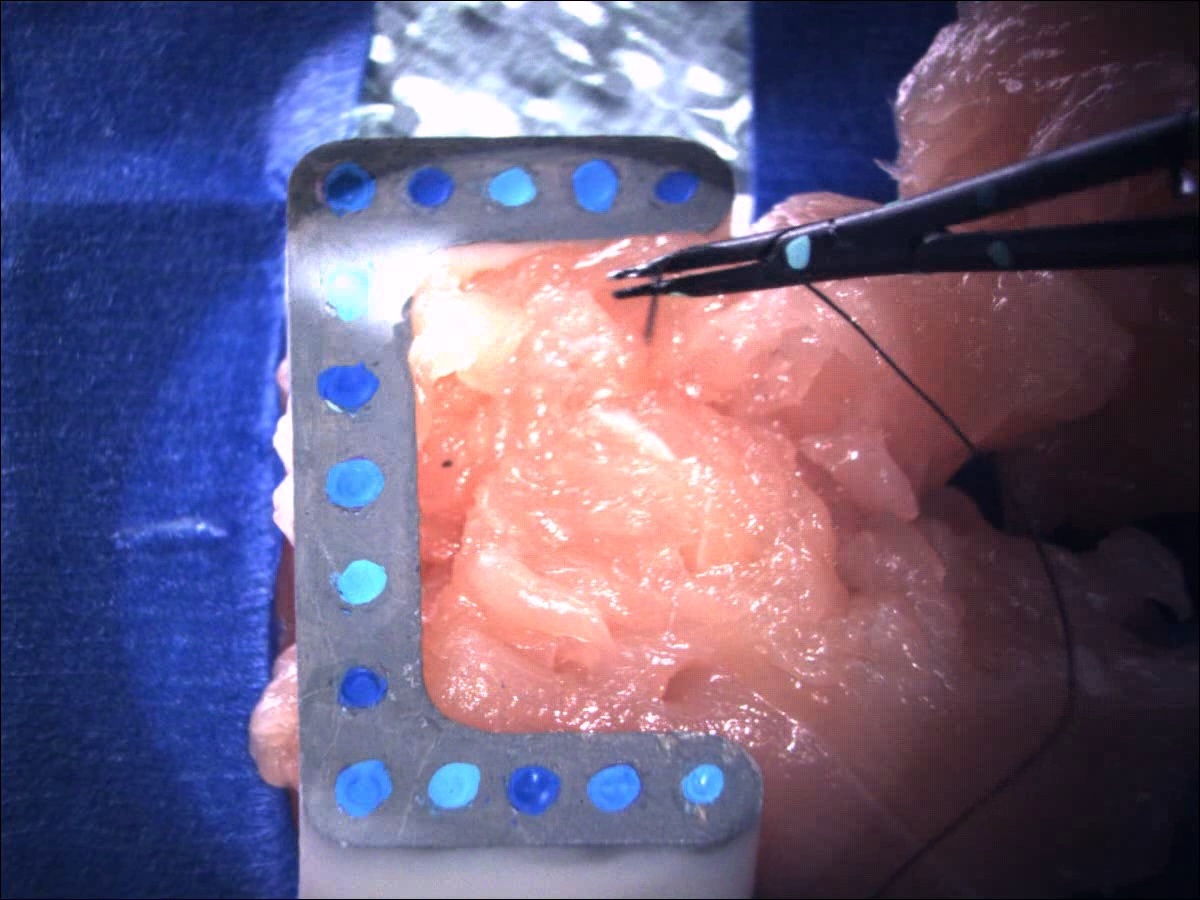
Detect color fiducials on tool
Triangulate the 3D tool tip position.
Motion Analysis:
Dependencies
Access to microscope and video capture computer
Chicken holding phantom (Background fiducial phantom)
Access to robot
Access to tools
Access to optical tracking system. Help from Paul to use system
Resolution Plan: Coordinate with Dr. Taylor and Paul.
Status: Resolved, I am no longer using the optical tracking system so it is no longer a dependency.
Milestones and Status
Milestone name: Record Ground Truth Data
Planned Date: 3/15
Expected Date: 3/31
Completed 3/31
Status: I am not using the optical tracking system for ground truth. Instead I recorded microscope video of the background “chicken holder” and the tool moving known distances. I moved the chicken holder along a graph paper background:
-
I moved the painted tool on top of a checkerboard background:
-
I also recorded video of freehand and robot-assisted suturing:
-
Milestone name: Compute Background Motion
Milestone name: Implement Video Tracking Algorithm
Milestone name: Frequency Analysis
code can filter for tremor and take the inverse DFT to compare the tool path with and without tremor.
Reports and presentations
Project Plan
Project Background Reading
Project Checkpoint
Paper Seminar Presentations
Project Final Presentation
Project Final Report
Project Bibliography
References:
[1] P. Grunert, K. Darabi, J. Espinosa, and R. Filippi, “Computer-aided navigation in neurosurgery,” Neurosurgical Review, vol. 26, no. 2, pp. 73-99, 2003.
Reading List:
S. Leonard, A. Reiter, A. Sinha, M. Ishii, R. Taylor, and G. Hager, “Image-Based Navigation for Functional Endoscopic Sinus Surgery Using Structure From Motion,” in SPIE, San Diego, 2016.
B. Allen, F. Kasper, G. Nataneli, E. Dutson, and P. Faloutos, “Visual Tracking of Laparoscopic Instruments in Standard Training Environments,” in MMVR, Newport Beach 2011.
R. Sznitman, K. Ali, R. Richa, R. Taylor, G. Hager, and P. Fua, “Data-driven visual tracking in retinal microsurgery. In Medical Image Computing and Computer-Assisted Intervention,” in MICCAI, Nice 2012.
Loubna Bouarfa, Oytun Akman, Armin Schneider, Pieter P. Jonker and Jenny Dankelman (2012) In-vivo real-time tracking of surgical instruments in endoscopic video, Minimally Invasive Therapy & Allied Technologies, 21:3, 129-134, DOI: 10.3109/13645706.2011.580764
W. Zhao, C. Hasser, W. Nowlin, and B. Hoffman, “Methods and systems for robotic instrument tool tracking with adaptive fusion of kinematics information and image information,” U.S. Patent 8108072 B2, Jan 31, 2012.
A. Cano, F. Gaya, P. Lamata, P. Sanchez-Gonzalez, and E. Gomez, “Laparoscopic Tool Tracking Method for Augmented Reality Surgical Applications,” in LNCS, vol. 5104, pp. 191-196, 2008.
Other Resources and Project Files


