Contact Us
CiiS Lab
Johns Hopkins University
112 Hackerman Hall
3400 N. Charles Street
Baltimore, MD 21218
Directions
Lab Director
Russell Taylor
127 Hackerman Hall
rht@jhu.edu
Last updated: 5/4/2019 4:11 pm
The goal of this project is to develop a projection mapping prototype that projects patient data (eg. CT/MRI scan model) in realtime so that it appears fixed onto patient body.
Projection Mapping, also known as Spatial Augmented Reality (SAR), is a frequently used method to add and visualize textures on real world objects. Static projection mapping is common in many applications such as multimedia shows, where the camera, projector, and object on which to project are all not moving. Dynamic Projection Mapping, which can deal with projections on moving targets or with a moving projector on a static target, is still a challenge. This project aims to apply dynamic projection mapping to the medical procedure called cranioplasty. Cranioplasty is a procedure used to treat and repair cranial defects using CCIs (custom cranial implants). The implants are usually made in oversized profiles and require resizing of the CCI to make it fit onto a specific patient’s skull. This resizing process is a challenging task for the surgeon because currently, the surgeon solely relies on visual analysis and manual hand modification. Therefore, we believe it has great value and potential to use projection mapping and robotic technology to assist surgical procedures such as cranioplasty to make the whole process faster and more accurate.
This project's specific aims are to:
The proposed solution is to develop a novel approach to cranioplasty using projection mapping. This compact system will consist of a depth camera and projector, assisted by a computer to handle the computation and processing. Ideally, the system will be able to project patient data (eg. CT data, oversized implant model, etc.) onto the patient while the surgeon does not need to wear any external hardware as is needed for most AR systems. Specifically, our system consists of a portable projector and the Intel RealSense Depth camera that can move around the skull model while projecting patient data onto it and retrieving 2D and 3D image data. The main parts of our technical approach consist of 3D reconstruction of CT scans, calibration of the camera-projector system, and registration. The 3D reconstruction will simply be done using existing software such as 3D slicer, and the other parts of the technical approach will be explained in the subsections below.
As illustrated in the figure, to summarize, before operating the camera-projector system, two steps need to be conducted. One is the calibration of the camera-projector system as noted by Huang et. al. The second step is to setup the marker-based registration through the pivot calibration and touching the anatomical landmarks. 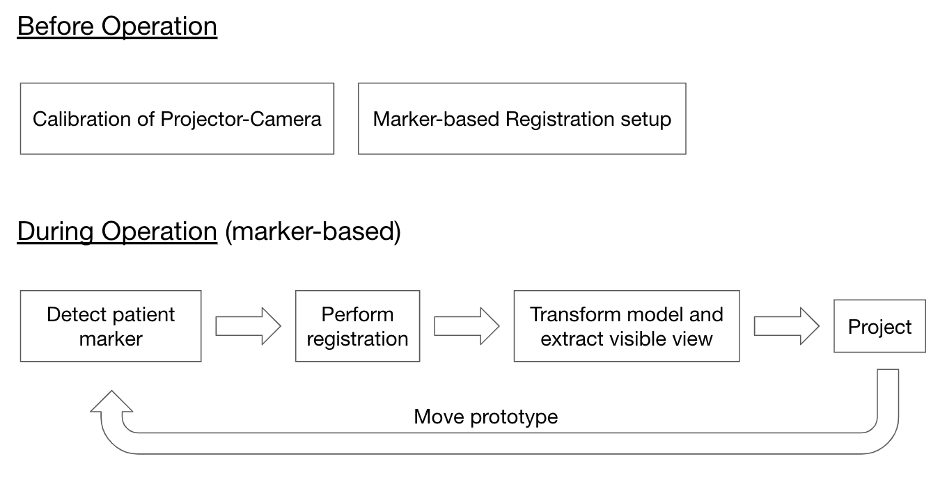 During operation, the system needs to be able to first detect the patient markers and then perform registration. The program then needs to extract the visible view of the 3D model and transform it properly to match the pose of the actual skull model. And lastly, that transformed model needs to be projected onto the skull model. And as the system is moved by the user, these steps need to be conducted over and over again.
In order to calibrate the camera and projector together, our procedure will build off the research done by Huang et. al. The figure illustrates most of the calibration setup. There will be a checkerboard placed in front of the projector and camera, and there will also be structured light patterns projected onto the same surface as the checkerboard. 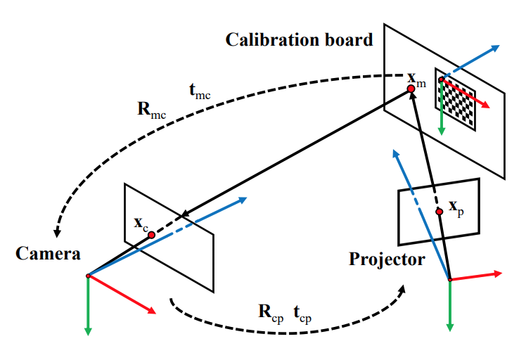 The first step would be to conduct a checkerboard calibration procedure in order to calibrate the camera. This will give us the intrinsic parameters of the camera along with the relative rotation and translation matrices between the calibration board pose and the camera. A homography between the calibration board pose and the camera image plane can then be calculated using formulas provided in their paper. The nodes in the structured light patterns then need to be undistorted and transformed to the calibration board model space. We can then perform a similar camera calibration procedure as in the first step but with the structured light nodes instead. We then know the transformations between the camera and the checkerboard as well as the projector and the checkerboard. This then allows us to find the transformation between the camera and the projector.
Update 4/17: All projector-related tasks will be done by Joshua. Therefore the projector-camera calibration procedure is outside the scope of my responsibilities for this project.
In order to determine what pose the actual skull model is in front of our camera-projector system, there needs to be some registration procedure that will be able to transform one set of points from the CT model to match the corresponding points on the skull model. In order to quickly achieve a fully working prototype, we have decided to first pursue a marker-based registration method.
As illustrated in the figure, we first need markers that are stationary relative to the skull model and also a tool with a marker on its end. 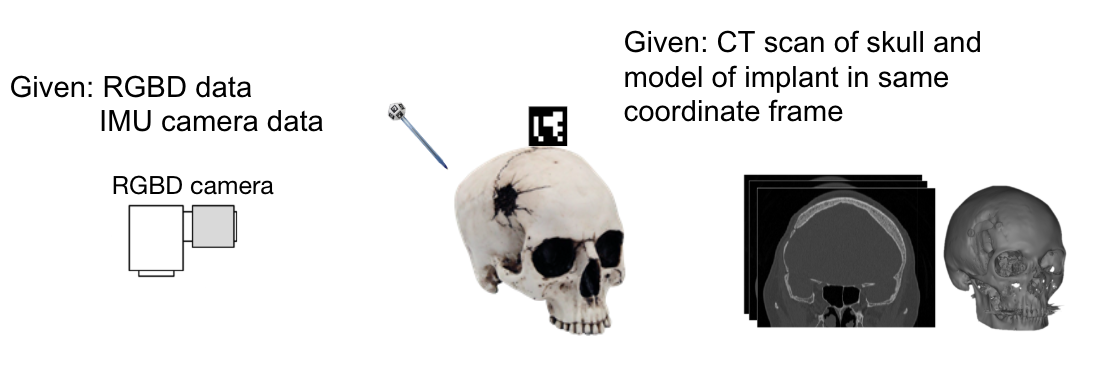 The markers then need to be detected through the images retrieved from the RealSense camera. After detection, a pivot calibration needs to be performed to obtain the transformation from the marker on the tool to the end of the tool. The tool can then be used to touch anatomical landmarks on the skull model, and the location of these anatomical landmarks needs to be recorded. With these locations, we can perform an initial registration with the points of the same anatomical landmarks that can be detected on the CT model. After this initial registration while the camera-projector is moving, the location of the same anatomical landmarks of the skull model can be obtained because we are able to detect the location of the markers stationary relative to the skull model. Registration can then be performed while the system is moving to obtain the proper transformation of the CT model to project onto the skull model.
Here are the models of our 3D marker tools and panels.
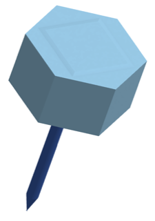
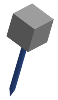
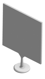
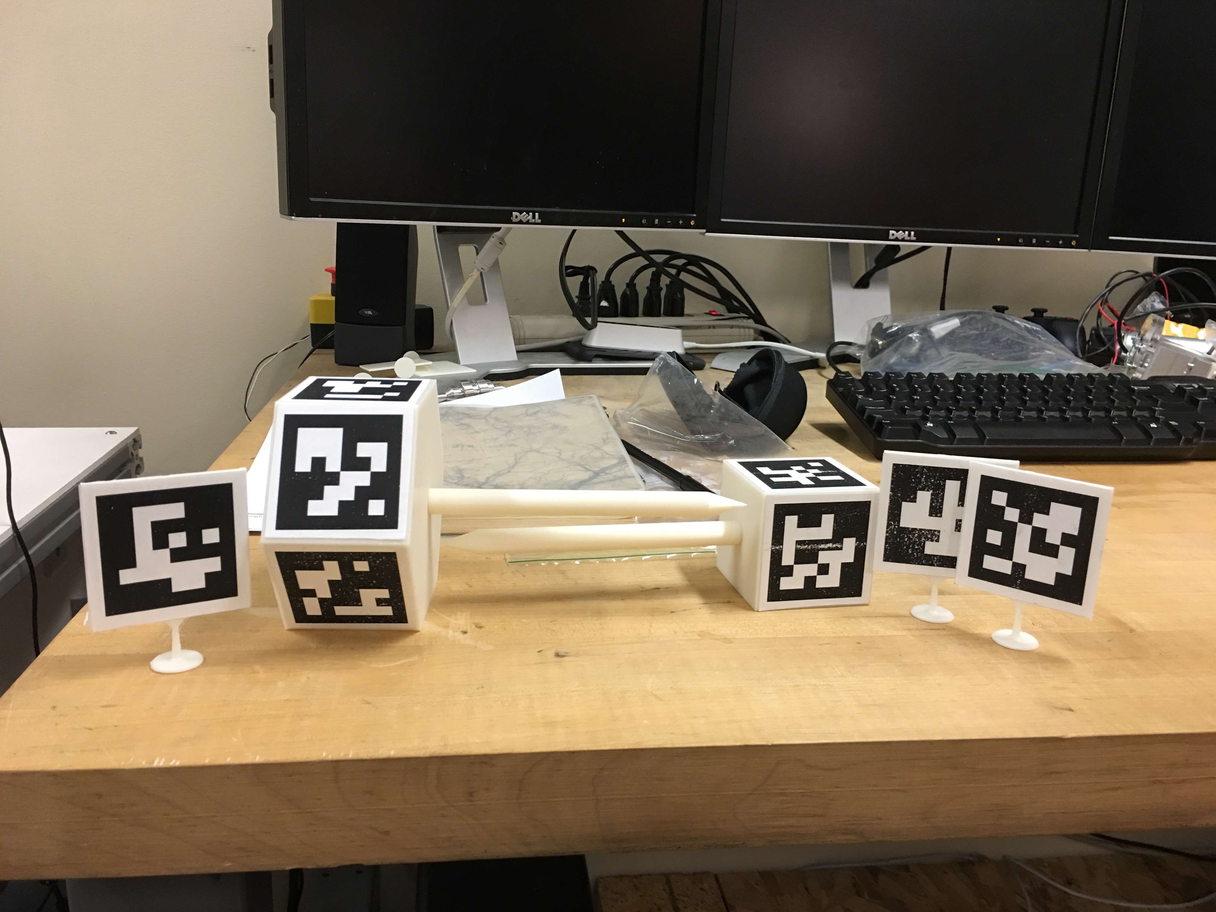
Here are the actual 3D-printed marker tools and panels.
However, before diving into the registration procedure, we will first conduct an accuracy evaluation for the ArUco marker detection and pose estimation. The setup for this evaluation will consist of a checkerboard and two markers printed on the same piece of paper, making them all coplanar. The camera will be calibrated, and the transformation between the checkerboard coordinate frame to the marker frame will be known. 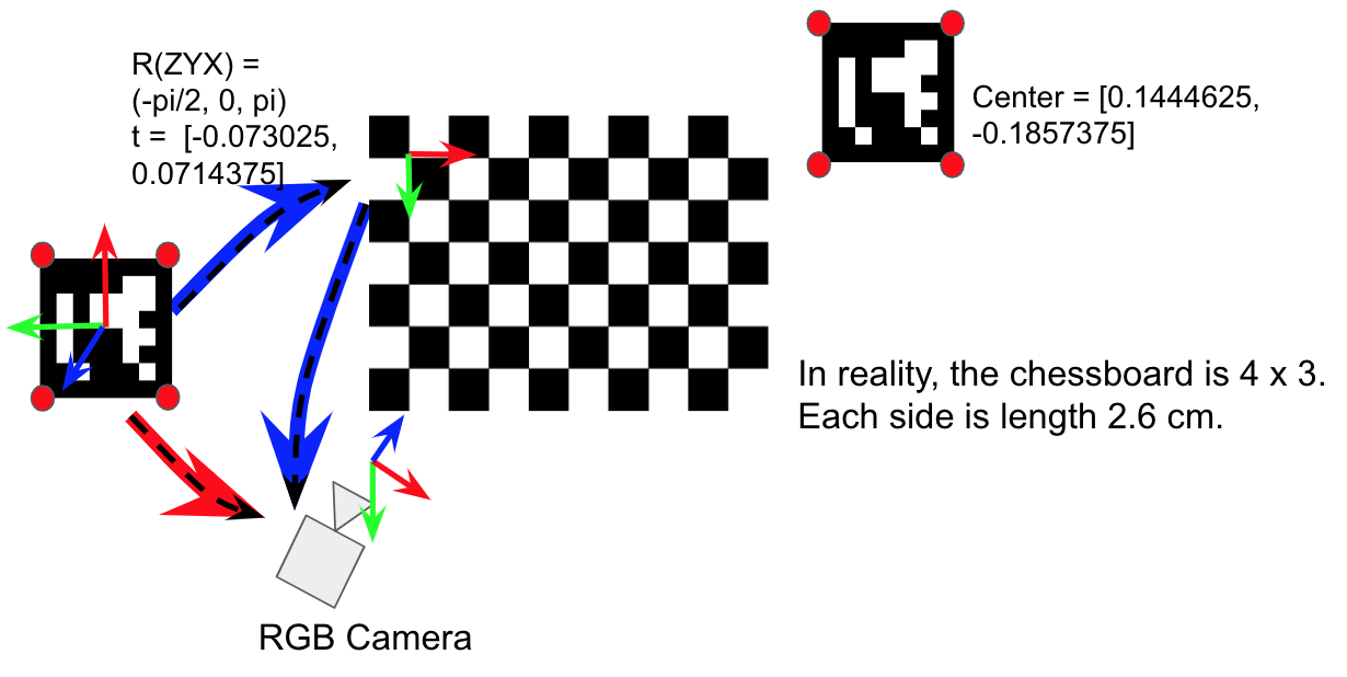 We can then compare the location of the marker using two methods to evaluate the pose estimation accuracy. The first will be through detecting marker directly from the RGB image of the RealSense camera, and the second method will be calculating the location of the marker using the checkerboard location that we have through the camera calibration. The second method will be what we deem as the “ground truth” transformation, and we will be evaluating the accuracy of the first method relative to the second. This accuracy can be evaluated at different poses, created by rotating the checkerboard surface at different angles with respect to the camera. In our evaluation, we will be setting the surface relative to the camera between 30 and 150 degrees in increments of 10 and calculating 30 transformations at each increment.
The reason we decided to use two markers instead of one is that the error in orientation (roll, pitch, yaw) obtained through the solvePnP function in OpenCV using only four corners from one marker is in the tens of degrees, which was an unacceptably large amount of error. The reason for this very large error is due to a phenomenon called pose ambiguity. Pose ambiguity occurs when the camera is observing the marker face close to straight on. In the left image of the figure below, assume that the four corners of the detected marker can appear anywhere within the red circles. The red circles indicate that each of these corners will have some noise associated with it and so the corner will not remain in one fixed location across multiple frames. Depending on where the corners are detected within those red circles, the most likely pose of the marker (or the one with the smallest reprojection error) can be illustrated using either one of the two cubes as illustrated in the right image of the figure below. The arrows represent the normals from the face of the marker. As can be seen in the image, the arrows representing the normals point in very different directions, which means that the obtained pose can be either exactly the one we are looking for or one that is drastically different from the correct one.
The same phenomenon is illustrated in the figure below. Essentially, a marker could be projected at the same pixels in the image with two different camera locations. And this ambiguity occurs more often as the marker appears smaller in the image because the errors in the corner estimation also grows. If the marker is observed from an oblique angle, the obtained pose can be said to be “more unique” because there could not be multiple different camera locations that would project the marker on the same pixels.
Here are the results of the evaluation.
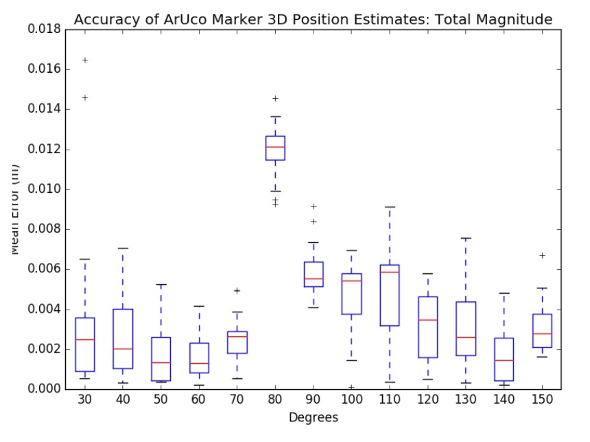
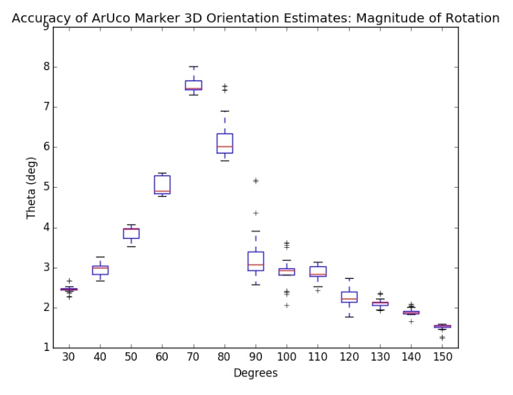
Let us first take a look at the left image in the figure above. This image is a graph of the error in the orientation of the pose estimation. The error is highest within the range of 60-80 degrees along with some outliers at 90 degrees, being as high as approximately 7-8 degrees. The error is lowest towards the ends of the range ( <40 and >120 deg), being as low as approximately 2 degrees. This confirms our hypothesis that the error in orientation is due to pose ambiguity when looking at the marker straight on. We deem this as a relatively acceptable range of error because a thesis by Pengju Jin, a Master's student in CS at CMU, confirms a similar amount of error in orientation. We also believe that this will be the largest source of error in our system's pipeline, and so one large part of our future work will be to reduce this pose estimation error. We also hope that a markerless version of registration will help remove this pose estimation error entirely and introduce a much smaller amount of error.
The right image in the figure above illustrates the error in position of the marker's pose. On average, the error magnitude is approximately 3-4 mm with a large uptick at around 80 degrees. There is no clear explanation as to why an uptick would occur at around 80 degrees, and we hypothesize that if we conducted multiple accuracy evaluations that this uptick would simply be an outlier. These results in position are promising because they are quite small given the fact that we are only using RGB images for pose estimation and have not utilized the depth map or point cloud data given by the Realsense camera. Both additional forms of data will be integrated in future work, and ideally the position error would decrease even further.
After ensuring relatively accurate detection capabilities, the next step in the marker-based registration is to perform the marker setup procedure. Suppose that the image below is a top view of the hexagonal marker tool. There is one marker on the top with an ID of 6, and there are markers on each side of the marker tool with IDs of 0-5. The tool coordinate frame is the same coordinate frame as the marker with ID 6. But because that specific marker will not always be in view of the camera, the transformations from each of the side markers to the marker tool coordinate frame need to be calculated. The way these transformations are calculated are by using the marker pose estimation function in OpenCV. As long as the marker with ID 6 and some other marker are in frame, the transformation from the camera to each of those markers can be found. Therefore, with those transformations, we can then calculate the transformation between the markers as well. In order to mitigate the effects of pose ambiguity because it is possible that the camera may face one of the markers relatively straight on, we implement a simple geometric-based filter. In this case, the shape of the tool is known to be a hexagon. Therefore, the difference in orientation between any two consecutive markers is approximately 60 degrees. As long as there are at least two side markers shown in view of the camera, the relative orientation between the side markers can be calculated and verified to be approximately 60 degrees. If that is not the case, then we can deduce that OpenCV returned an erroneous pose for at least one of the markers and can ignore the calculated transformations for that frame.
A video of the marker setup procedure can be accessed here. In the video, I bring the marker tool in view of the camera, and as long as the marker representing the tool coordinate frame and some side marker is in view of the camera, then the transformation from the side marker's frame to the tool coordinate frame can be calculated and saved.
Although this process only needs to be conducted once, we conducted an accuracy evaluation to see how reliably these transformations can be calculated. The image below illustrates the result of 30 different instances of the marker setup procedure performed. The values along the x-axis display α, the difference in orientation between the two markers whose IDs are represented by the subscripts. On average, the magnitude of the error in orientation between any two consecutive markers is approximately 1 degree and at maximum 3 degrees.
After performing the marker setup, the pivot calibration procedure needs to be performed for each tool to be used. The math behind the pivot calibration procedure can be seen in the image below taken from Dr. Taylor's CIS I class. The ground truth value for the hexagonal marker tool is that the tip of the tool is at [0, 0, -0.210] relative to the tool coordinate frame. Using pivot calibration, the values achieved are [0.00812451, -0.00558087, -0.21730515]. Although the error along each axis in the values obtained are approximately 6-7 mm, we hypothesize that this error can be reduced if the marker pose estimation error can also be reduced.
A video of the pivot calibration procedure can be accessed here. For the purpose of a demo, I am pivoting the hexagonal marker tool on a piece of cardboard. The video shows that no matter what markers are shown to the camera, the appropriate transformations can be successfully calculated, and the user can determine when to record a point to then perform the necessary calculations.
This procedure also only needs to be performed once for each marker tool, but we decided to perform an accuracy evaluation to determine how reliably the tip position can be calculated. According to the results shown in the figure below, the approximate error along each axis is 5-10 mm and can be as high as 30 mm. For these results, we performed 10 different pivot calibrations, collecting 5 points for each one. We believe that the error is highly dependent on how many points are obtained by the user and once again dependent on how accurately we can determine the pose of the detected markers.
Through the accuracy evaluations and graphs shown above in this section, it was determined that the system would be insufficiently accurate and too unstable. We then decided to port all existing software to ROS and utilize the pre-existing ar-track-alvar package, which performs the AR marker pose estimation. Through basic preliminary testing, the ROS AR tracking package has a translation error of approximately 8-10 mm and a negligible standard deviation, meaning it produces very stable estimations.
The figure below shows the ROS network of nodes I developed.
Using the ar-track-alvar package, we perform a pivot calibration for our marker tools relative to the coordinate frame of a stationary marker. This outputs the coordinate of the tip of the tool relative to the tool's coordinate frame. This tip coordinate is then used to calculate the user-recorded points of distinct anatomical landmarks on the patient's skull relative to a marker fixed rigidly on the patient's skull. The recorded points form a point cloud data of the patient's actual skull. This point cloud along with the point cloud formed from the STL skull model are inputs for the python registration package, PyCPD. This package treats the alignment of two sets of data as a probability density function and uses an algorithm called Coherent Point Drift. From this package, a transformation between the stationary marker on the skull and the STL model can be found.
This transformation then allows my system to be combined with the projector and visualization work done by Joshua Liu and Weilun Huang. With this combined system, we can produce a window that displays a view of the skull STL model rendered from the perspective of the projector.
An evaluation of the accuracy of this marker-based registration still need to be done.
Another method under consideration is a markerless registration procedure. The underlying idea of this is that the point cloud data from the RealSense camera needs to be registered to the point cloud of the 3D model. For the point cloud data from the RealSense camera, there is unfortunately not a clear way to automate the process of segmenting the desired object. Most research focuses on systems where there is a static camera and a moving object or both a moving camera and a moving object. In these cases, methods such as optical flow can be used to subtract the background because the object relative to the camera moves in a different way than the background relative to the camera. However, in this situation, the camera is the only one moving, and therefore the desired object and the background move in the same manner relative to the camera. 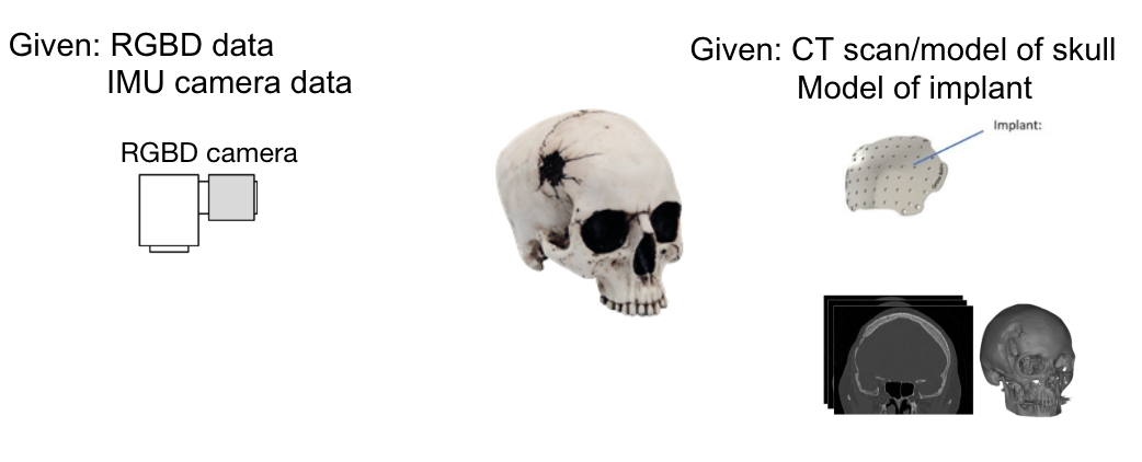
The first idea is to collect a high density of points around a unique anatomical feature using the marker tool. One such anatomical feature would be the nose. After obtaining such a point cloud, we hypothesize that because this feature is so unique, the registration procedure we use should be able to match our unique point cloud to the correct area of the 3D model's point cloud. The next idea is to perform this markerless registration with the raw Realsense point cloud data. This bypasses the need for any marker-related tool or software. Ideally, the raw point cloud data we retrieve from the Realsense camera can be quickly matched to the 3D model's point cloud.
| Dependencies | Solution | Expected Date | Needed by |
|---|---|---|---|
| Computer | Personal laptop | Done | |
| Access to BIGGS lab | Ask Professor Armand | Done | |
| Access to Intel RealSense SDK 2.0 | Downloaded | Done | |
| Access to Intel RealSense camera | Bought | Done | |
| Access to Open3D library and OpenCV | Installed | Done | |
| Access to projector | Currently have one, may upgrade | Done | |
| Holding mechanism for projector and camera | Built by Joshua | Done | |
| Construct ArUco markers and marker tool | 3D print our own | Done | |
| Construct ArUco marker fixture | 3D print our own | Done | |
| CT scan reconstruction software (eg 3D slicer) | Ask Professor Armand and lab mates | Done | |
| Obtain data (scans and models of skulls) | Currently have molds, need corresponding scans | Done |