Table of Contents
Ultrasound Needle Detection Using Mobile Imaging
Last updated: May 7, 2015 and 7:31PM
Summary
Combining the information from an active ultrasound source as well as the information from conventional imaging to localize a needle-tip are the main topics of this project. In addition, there will be some computer vision topics including image segmentation and optical tracking. The goal of this project is to provide a more simple and inexpensive method to calculate the 3D position of a needle point using only an ultrasound probe and conventional camera imaging.
- Students: Phillip Oh, Bofeng Zhang
- Mentor(s): Alexis Cheng, Dr. Emad Boctor
Background, Specific Aims, and Significance
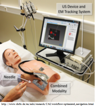
Image guidance is useful in surgery to help surgeons track the location of their tools in potentially very sensitive parts of the body in order to increase surgery accuracy and to decrease risk of harm to the patient. There are many ways to do this, but the advantage of ultrasound is the fact that it can be done easily intraoperatively without exposure to radiation. In order for ultrasound to be used, a calibration must be done between ultrasound coordinates and the tracker of the tool. Many methods are performed to do this; however, the precision of these methods can be improved, as EM tracking for registration results in a 3 mm error. Current methods are also unable to track the needle point if it is outside the ultrasound plane, knowing only the point where the needle crosses the plane.
The advantage of using the active echo technique combined with the active point out-of-plane is an accurate calibration which can track the needle point outside of the ultrasound plane, using only an ultrasound probe, and active source on the needle point, and camera, which reduces equipment needed for calibration and increases precision.
Deliverables
- Minimum: (Expected by March 21, 2015 - Completed April 30)
- 3D position of probe-tip offline, more specifically
- Segmentation of needle in images taken from webcam/iPhone
- iPhone mount to ultrasound probe
- Ultrasound calibration
- Recover needle-point position using US and iPhone images
- Expected: (Expected by April 4, 2015 - Completed May 3)
- Analysis and validation of technique
- Maximum: (Unable to be completed)
- Real-time 3D position of probe-tip using live-feed from iPhone camera and US machine
Technical Approach
Overview
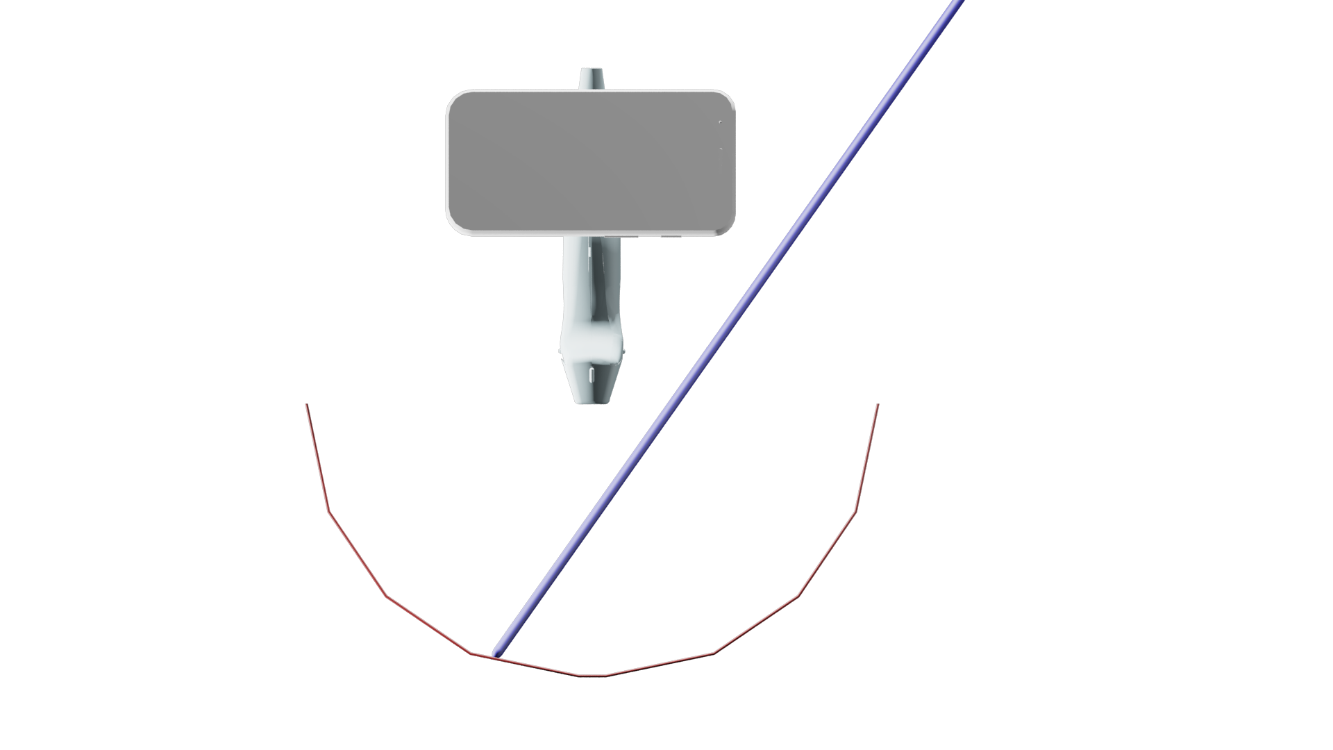
In order to allow for tracking of the needle tip even when out of the ultrasound image plane, the solution uses needle with an active piezoelectro (PZT) element attached at the tip. The ultrasound transducer is switched to listen only mode. It listens to the synchronized pulses from the PZT element. The data that the ultrasound transducer collects are the transducer element that is closest to the PZT element and the distance from the PZT element to the closest transducer element. This data gives a subset of locations where the PZT element may be. This subset of locations forms a semicircular arc that intersects with the ultrasound image plane perpendicularly. In order to find the location of the PZT element within this subset, a conventional image from a smartphone camera attached to the ultrasound transducer is acquired. This smartphone image captures the external portion of the needle. From this image, the plane that the needle lies on can be determined in the camera coordinates. The arc in ultrasound coordinates and the plane in camera coordinates must then be transformed into the same coordinate system using a pre-computed ultrasound calibration. After the arc and the plane are brought into the same coordinate system, their intersection is then determined. A single intersection point can be extracted, thus determining the position of the PZT element, which is also the needle tip.
Workflow
 1. Capture images of needle using cell phone camera.
2. Process images: Image segmentation of needle to find two pixels along the needle.
3. Use Camera calibration to calculate the vector along which the two pixels lie in camera coordinates. Then use the these two points, along with the origin in camera calibration, as three points (p1, p2, p3) on the plane we want to intersect.
4. Simultaneously, find the position of the needle tip, point a, where the ultrasound probe detects the active source on the tip of the needle.
5. The active source creates a cylindrical ultrasound signal. This signal can be detected by the ultrasound even when out of plane, but does not provide any information about whether the point is in plane or not. Thus the distance from the ultrasound probe is known, as well as where along the probe, but the elevational information is unknown. This creates an arc where the radius of the arc is axial distance of point a, the center of the arc is the lateral distance along the probe, and the plane of the arc is perpendicular to the ultrasound plane.
6. Thus, we use this point a to create the arc equation. The arc is modeled as two half circles with a linear portion in between representing the elevational thickness of the ultrasound probe.
7. In order to intersect the arc and the plane, they need to be in a common coordinate system. This is done through ultrasound calibration, and the three points on the plane in camera coordinates are transformed to ultrasound coordinates.
8. Because the arc provides all but the elevational location of the needle tip, and the needle lies along the plane we calculated previously, the intersection will provide full 3D position of the needle tip. This intersection is calculated by finding the angle t which fit the following criteria:
- A point which is colinear with a point on the circle and a point on the plane, represented by C-p1.
- A point which satisfies the above and is coplanar to the plane, which occurs when the above line and the normal to the plane are perpendicular, i.e. their dot product is 0.
Finding the angle t, and substituting it into the arc formula will provide the needle tip location.
9. Because the arc is modeled as two half circles, there will be two solutions to the equation. However, the point outside the body, i.e. y < 0, is discarded giving us the final location.
An animation showing the approach can be seen here.
Experimental Setup
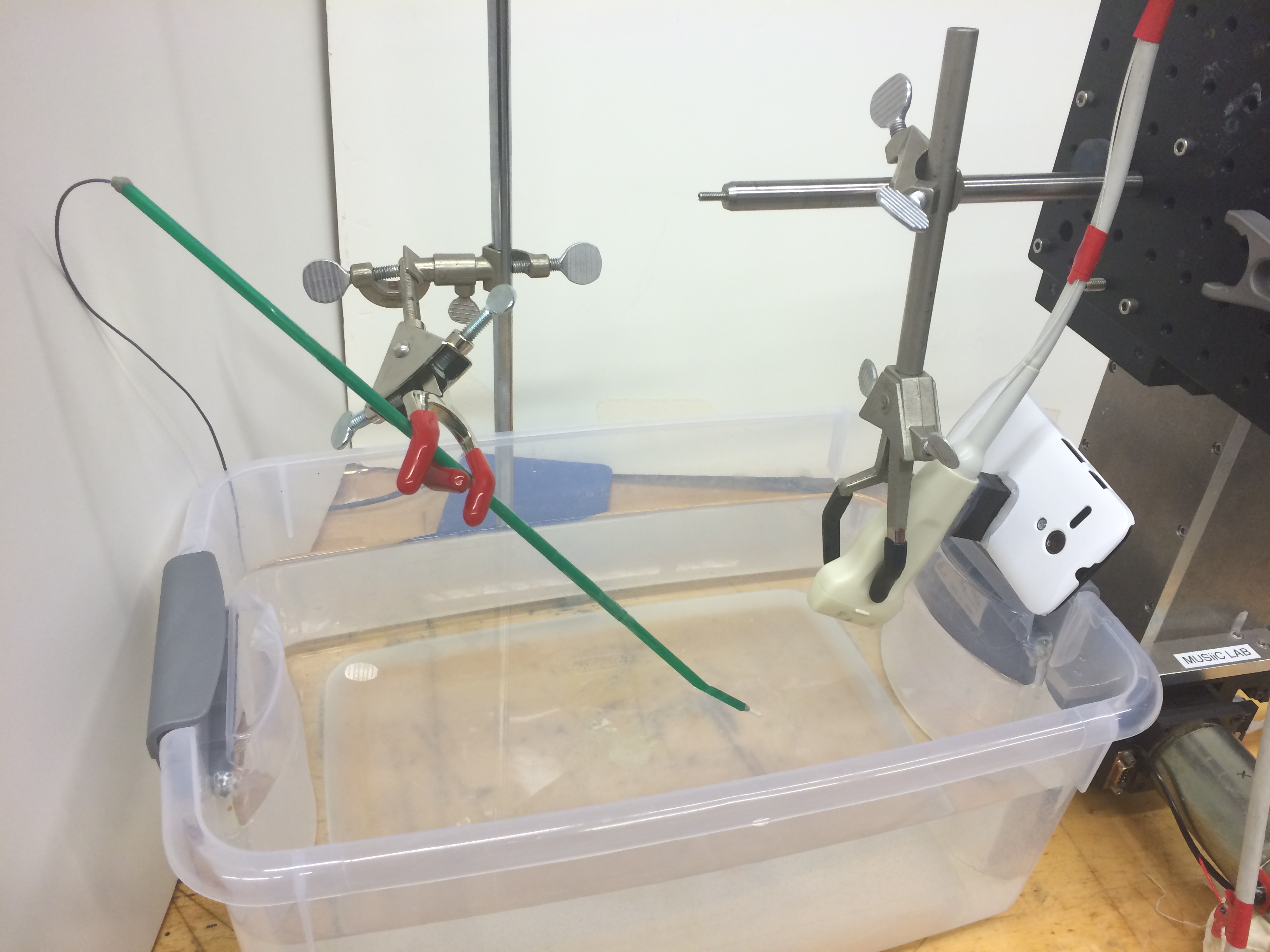
A mock tool was constructed using a straw, with an active piezoelectro (PZT) element is attached to the tool tip, transmitting synchronized pulses to the receiving US transducer. The “needle” was fixed in two different poses in a water bath, while a cell phone mounted US probe was moved in linear 4mm steps in the 3 orthogonal directions independently. From the original in-plane point, the probe was moved 12-16 mm in each direction.
Accuracy was measured by how out-of-plane computed points were that were experimentally placed in-plane. Precision was measured by the relative distance between two calculated points compared to the known distance (4mm).
Results
| Accuracy | RMSE |
|---|---|
| Pose 1 | 0.6333 mm |
| Pose 2 | 0.1752 mm |
| Precision | |
|---|---|
| RMSE | 0.8608 mm |
| Standard Deviation | 0.8600 mm |
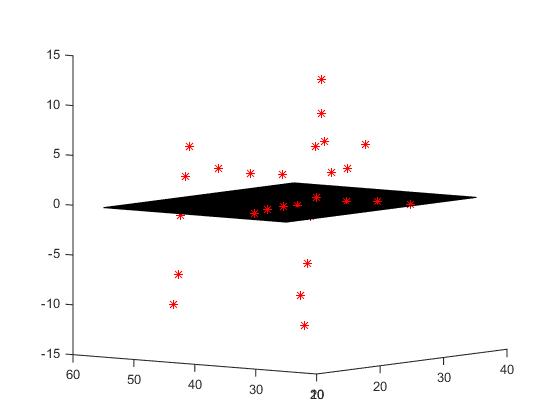
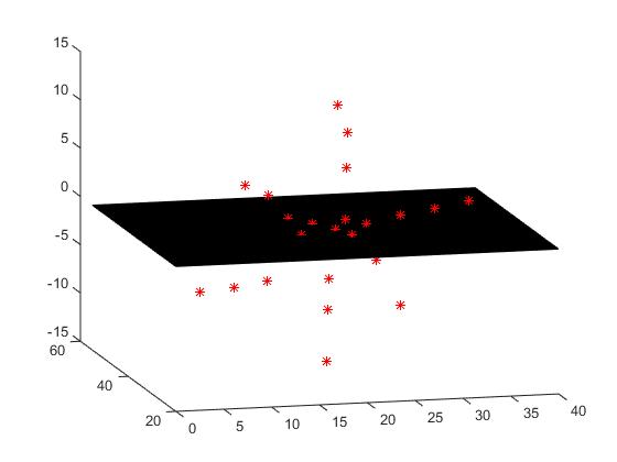
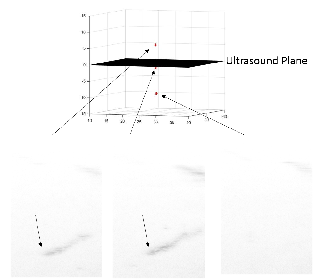
Pose 1 (Left) and Pose 2 (Right) locations of the needle points (red points) on various positions of the US probe.
The black plane represents the ultrasound imaging plane.
Significance
We have shown that this method is able to localize a needle tip both in-plane and out-of-plane positions to some degree of accuracy. This is advantageous to ultrasound only guidance methods which can only detect in-plane points, and also advantageous to electromagnetic tracking methods as it only requires any mobile device with a camera and an active source at the tool-tip to work.
Below we see the inverted B-mode image in 3 different positions of the probe. The left and center images are on either side of the ultrasound plane, and the right image shows a position where the ultrasound alone is too far away to see the needle. Notice the left and center images are very similar, and there is no way to differentiate which side of the ultrasound probe the needle is on. However, above, we see the corresponding locations of the needle by out method, which clearly differentiate the 3 positions.
Future steps on this work will involve a real-time, mobile app based implementation of this system, as well as testing in more realistic phantoms using a tool more similar to that used in actual surgery.
Dependencies
* Access to Ultrasound machine, needle, webcam, active point
- Needed equipment to do the actual needle guidance. The project will be unable to complete without these. Webcam segmentation can be started on with our own equipment if equipment is not available.
- Contact Dr. Boctor for permission and other labs if not met.
- Deadline for resolving March 7, 2015
- Dependency met February 27, 2015
* Wyman 3D printer access
- Needed to print iPhone camera holder for optical tracking of needle. If not met, a webcam can suffice although the accuracy will be affected.
- Contact Neil Leon, otherwise try to get permission to use DMC or BME printers.
- Deadline for resolving March 1, 2015
- Dependency not needed as we decided to glue a Lego block to an iPhone case instead of making a holder.
* Access to labs: Robotorium, MUSiiC lab in Robotorium
- Needed to gain access to above equipment to collect data and run experiments, and may slow or prevent access to lab if unmet.
- Contact LCSR admin office, and we will have to contact one of our mentors for access if this is unmet.
- Deadline for resolving March 1, 2015
- Dependency met February 27, 2015
* UR5 robot arms
- Needed for running validation trials and will be unable to run accurate trials without the arms.
- Contact Dr. Armand's Biggs lab, otherwise ask Alexis for alternate options
- Deadline for resolving March 22, 2015
- Dependency not needed. Movement of probe was carefully measured using mount.
* Meetings with Alexis
- Needed for asking any questions and touching base on progress of the project, and may not be able to communicate our progress and concerns as regularly or clearly if unmet.
- Contact Alexis, and will have to communicate by email if unmet.
- Deadline for resolving February 16, 2015
- Dependency met February 11, 2015
* Meetings with Dr. Boctor
- Needed for guidance as well as for touching base on progress of the project, and may not be able to communicate our progress and concerns as regularly or clearly if unmet.
- Contact Dr. Boctor, and will have to communicate by email if unmet.
- Deadline for resolving March 1, 2015
- Dependency met April 5, 2015
Milestones and Status
- Milestone name: Needle Segmentation from Camera Image
- Planned Date: March 7, 2015
- Expected Date: March 7, 2015
- Status: Completed March 24, 2015
- Milestone name: Compute Equation of Plane from Camera
- Planned Date: March 7, 2015
- Expected Date: March 7, 2015
- Status: Completed March 24, 2015
- Milestone name: CAD Model of camera holder
- Planned Date: March 9, 2015
- Expected Date: March 9, 2015
- Status: Decided to use Lego block glued to phone case instead
- Milestone name: Ultrasound Calibration
- Planned Date: March 30, 2015
- Expected Date: April 1, 2015
- Status: Completed April 1, 2015
- Milestone name: Offline Calculation of Needle Tip
- Planned Date: April 6, 2015
- Expected Date: April 13, 2015
- Status: Completed April 30, 2015
- Milestone name: Experiment for method validation in water
- Planned Date: April 13, 2015
- Expected Date: April 25, 2015
- Status: Completed April 25, 2015
- Milestone name: Analysis and validation of results
- Planned Date: April 13, 2015
- Expected Date: April 25, 2015
- Status: Completed May 1, 2015
- Milestone name: Implementation of real-time system
- Planned Date: April 27, 2015
- Expected Date: May 4, 2015
- Status: Scrapped due to time constraints
Reports and presentations
- Project Plan
- Project Background Reading
- See Bibliography below for links.
- Project Checkpoint
- Paper Seminar Presentations
- Project Final Presentation
- Project Final Report
- See below for project source code
Project Bibliography
Beigi, Parmida, et al. “Needle detection in ultrasound using the spectral properties of the displacement field: a feasibility study.” SPIE Medical Imaging. International Society for Optics and Photonics, 2015.
Beigi, Parmida, and Robert Rohling. “Needle localization using a moving stylet/catheter in ultrasound-guided regional anesthesia: a feasibility study.” SPIE Medical Imaging. International Society for Optics and Photonics, 2014.
Cheng, Alexis, et al. “Active point out-of-plane ultrasound calibration.” SPIE Medical Imaging Conference, Orlando, 21-26 February 2015. 9415-30.
Guo, Xiaoyu, et al. “Active Echo: A New Paradigm for Ultrasound Calibration.” Medical Image Computing and Computer-Assisted Intervention–MICCAI 2014. Springer International Publishing, 2014. 397-404.
Heikkila, Janne, and Olli Silvén. “A four-step camera calibration procedure with implicit image correction.” Computer Vision and Pattern Recognition, 1997. Proceedings., 1997 IEEE Computer Society Conference on. IEEE, 1997.
Other Resources and Project Files
- Source code on Dropbox
- Results Videos:
