Table of Contents
Head Mounted Display Integration for Orthopedic Surgery
Last updated: May 18 and 12:29PM
Summary
The project focuses on using augmented reality to visualize the occluded part of the needle in
HoloLens. The whole process also requires tracking the needle position and estimating the
needle tip location. The diagram for the system set-up is showed in the graph below. The main
hardwares needed for this project are, a RGBD Camera (Intel RealSense SR300) and a HoloLens.
- Students: Zhuokai Zhao
- Mentor(s): Sing Chun Lee, Long Qian, Javad Fotouhi, Alexander Barthel, Dr. Bernhard Fuerst, Dr. Nassir Navab
Background, Specific Aims, and Significance
Orthopedic surgery is the general name of different types of surgery that concern with the
musculoskeletal system. It includes treatments to musculoskeletal trauma, spine diseases,
infections, tumors and congenital disorders. Orthopedic surgery often requires placing and
removing a rigid object during the operations. Therefore, image-guided systems are widely used,
especially in minimally invasive orthopedic operations.
Current workflow starts with acquiring multiple X-ray images from different views to locate the
point of entry, under the help of a reference tool. Next, the medical instrument is invaded and
moved inside the patient’s body with small displacements. To determine the direction of the next
movements, a set of anteroposterior X-ray images are acquired during each movement, until the
target is reached. It could be easily seen that the current procedure produces a large amount of X-ray doses, while with less efficiency on guidance. Low-Efficiency procedure not only frustrates
surgeons, but also could cause damages to soft issues and the nervous system, which further lead
to severe post-operative sequelae. Therefore, we propose a solution to use HoloLens to display
the needle part that is within the patient’s body to better guild the surgeon and protect the patient.
Deliverables
- Minimum: (Expected by 3/26)
- Camera calibration algorithm for RGBD camera and the head mounted display device
- Marker tracking algorithm used to track needle movements
- Skin model detection algorithm with basic thresholding on point clouds
- Roll out HMDs to the hospital operating room
- Expected: (Expected by 4/29)
- Needle location and orientation estimation in 3D space
- Algorithms that determine which part of the needle is within the patient’s body
- Display the part of the needle that is within the patient’s body via HoloLens
- Maximum: (Expected by 5/6)
- Implementation of different perceptual cues
- Evaluation and comparison of different visualizations
Technical Approach
The system setup is showed in the figure below. RGBD CameraTMarker and HoloLensTMarker denote the tracking result from marker to RGBD camera and HoloLens respectively. Similarly, HoloLensTRGBD Camera represents the calibration result between the two devices, which is the transformation matrix from RGBD camera to HoloLens. MarkerPneedle tip indicates the needle tip position with respect to marker coordinate.
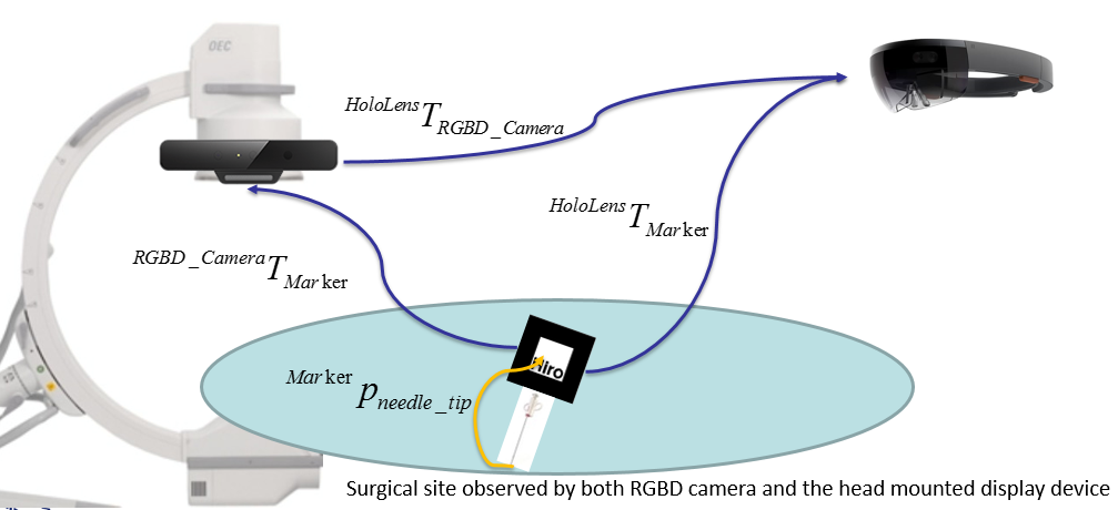
Since the big picture of this project is to augment a virtual needle which aligns with physical needle, the complete approach can be divided into five main sections: needle orientation tracking; needle tip position estimation; camera to HoloLens communication; outside/occluded needle parts classification; and virtual needle augmented visualization. The method of using both RGBD camera and HoloLens was designed and developed at the beginning, but was replaced by the idea of using the HoloLens only in the end.
Needle Tracking with ARToolKit
Needle Tracking using PC and RGBD Camera
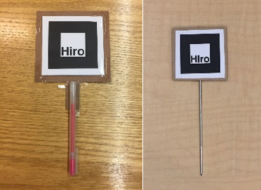
In this approach, the needle is tracked by an external PC-connected RGBD camera, through a marker that is rigidly attached to a tool. As showed in the figure below, the tool on the left is used while developing and the tool on the right is the real medical tool used for demo. The tracking algorithm is implemented with the use of ARToolKit.
The tracking result was formatted to be the 4×4 homogeneous transformation matrix from marker to the RGBD camera, which is denoted as RGBD CameraTMarker.
Needle Tracking using HoloLens
With the front-facing camera (locatable camera) available on HoloLens, marker tracking using ARToolKit could ideally be very similar to using the RGBD camera with PC. However, since HoloLens runs on Universal Windows Platform (UWP), which uses different tools and run-time libraries than on the PC, ARToolKit does not support any UWP devices. Therefore, the solution implemented above could not be deployed to HoloLens directly. Luckily, a third-party library called HoloLensARToolKit, which contains similar functions included in the normal ARToolKit, has been published [1] and is ready to use. Same as before, the tracking result was formatted to be the 4×4 homogeneous transformation matrix from marker to the HoloLens, which is denoted as HoloLensTMarker.
Needle Tip Position Estimation
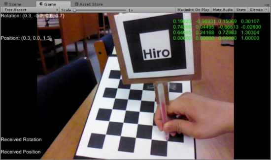
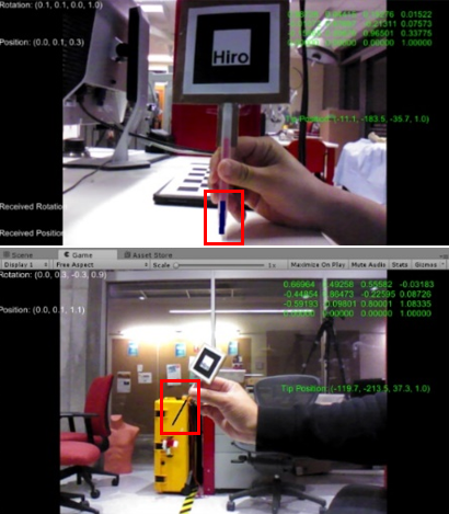
The needle tip position is estimated through the pivot calibration. A program was developed in Unity. It runs in real-time to save all the transformation matrices from marker to camera in a text file. As showed below, the green 4×4 matrix on the upper right corner indicates the current transformation matrix from marker to the camera.
The tip position is kept unchanged for the whole time while moving the marker around for transformations of different poses. For each pose, below relationship stands.
CameraTMarker * Markerptip = Cameraptip
which is the same as
CameraRMarker ∙ Markerptip + CamerapMarker = Cameraptip
where CameraRMarker and CamerapMarker are the rotation and translation parts of homogeneous transformation CameraTMarker.
Since the needle model is rigid, Markerptip and Cameraptip do not change over time. The above equation is further manipulated to be
[CameraRMarker - I]∙[Markerptip Cameraptip]T = -CamerapMarker
By solving the least square solution of the above equation using the transformation results collected, the tip position with respect to the marker coordinate is obtained.
RGBD Camera to HoloLens Communication
To calibrate between RGBD camera and HoloLens, the system needs two requisites: both RGBD camera and HoloLens must see the marker that is attached to the needle simultaneously; the RGBD camera is able to send the transformation result, RGBD CameraTMarker, to HoloLens in real time. The first condition is required because it makes the two inputs, RGBD CameraTMarker and HoloLensTMarker available. The second condition is important because only by that, the transformation from RGBD camera to HoloLens, HoloLensTRGBD Camera, can be calculated within HoloLens as
HoloLensTRGBD Camera = HoloLensTMarker-1 ∙ RGBD CameraTMarker
The sending and receiving parts are implemented through the User Datagram Protocol (UDP), which is a communication protocol that is mainly used for establishing low-latency transmissions.
Needle Parts Classification
The first key of classifying the outside and occluded parts of the inserted needle is the successful identification of the patient’s body surface. Two approaches have been made during the research process. The first one is to use the RGBD camera to generate and segment the point cloud data of the patient’s body. This approach was later found to be inefficient during operation because of low transmission rate between RGBD camera and HoloLens via UDP communication. The second approach takes advantage of the HoloLens’s spatial mapping function to detect the surface mesh that is within the user’s sight. Although only the second approach was chosen as the final implementation method, both approaches are presented and discussed in this section.
Surface Detection with RGBD Camera
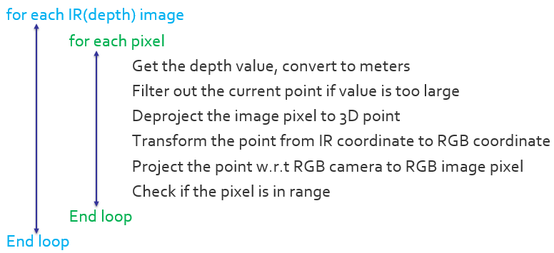
To generate the point cloud data that represents the patient’s body using RGBD camera, the entire process could be divided into three steps. The first is to generate point cloud data for all the objects that the camera sees; the second is to segment the point cloud based on surface normal; the third is a further segmentation that uses color. The RGBD camera has one RGB camera for color captures (RGB image) and one Infrared camera for depth captures (depth image). The relative position and orientation between the two cameras do not change. The algorithm that implements the first step could be presented as:
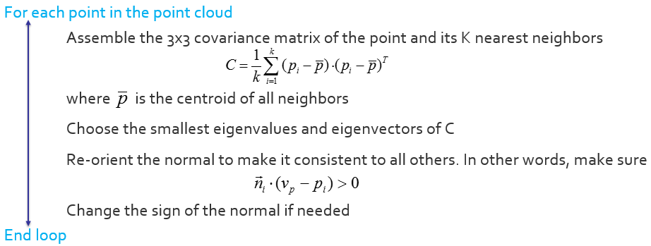
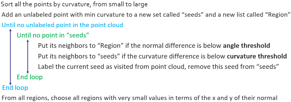
The main idea of constructing the point cloud data in the above algorithm is to find the correspondence between RGB and IR pixels in each video frame to generate the point cloud result. After obtaining the result, segmentation starts with normal-based region-growing algorithm. [2] Before diving into the segmentation process, there is one more question that needs to be solved – generating normal cloud that corresponds to the point cloud. The algorithm used is concluded below. [3]
After both the point cloud and the normal cloud have been determined, the normal-based region growing algorithm could be implemented, with the details concluded below.
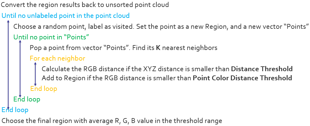
Since in the scope of this project, the shape of the phantom that represents the patient’s body is a cube, the algorithm picks the cluster with normal that is pointing up to be the final segmentation result. However, it is likely that the background environment has the same surface existing, which causes noises in the segmentation result. To further address the issue, the normal-based segmentation result is converted back to unsorted point cloud, and is used for color-based region-growing algorithm. [4] The detail of the algorithm is showed below.
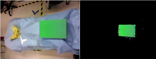
By choosing the appropriate thresholds, color-based region-growing algorithm gives final segmented cluster that satisfies the color requirement of the patient body surface. With the combination of the normal-based segmentation algorithm, the target surface could be successfully segmented even in a relative complex environment, which contains objects that is geometrically very similar to the target object. The segmentation results are showed below. The left image indicates the true environment while the right image shows the segmented point cloud result.
Although the result shows quite satisfying and stable during the experiment, unfortunately, it was proven to be not useful after trying to send the point cloud data over the RGBD camera – HoloLens communication in real-time. The transmission rate as well as the processing ability at HoloLens are not fast enough to handle the point-cloud data in real-time. The issue leads to a more direct and efficient implementation method introduced below.
Surface Detection with HoloLens
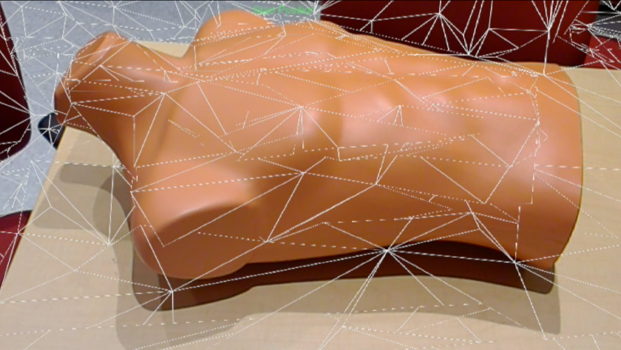
HoloLens can be used to detect the surrounding environment through its spatial mapping ability. More specifically, spatial mapping could be implemented to provide virtual surface mesh on the real-world surfaces. [5] The surface mesh result, rendered as white triangular, is showed in the picture below.
Virtual Needle Augmented Visualization
Augmentation Visualization on PC
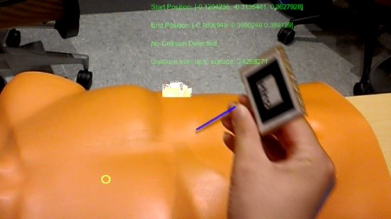
The augmentation visualization program runs within Unity on PC, with ARToolKit imported as an external asset. In real-time, the program captures the marker’s position and orientation, loads the pivot calibration result, and computes the current needle tip position with respect to the camera. The length of the virtual needle is user-defined, and the focus is to align the virtual needle alone with the physical tool. The result with the virtual needle augmented in color blue is showed in the figures below. The first one was augmented on the initial tool model with 3cm virtual needle length. The second one was implemented with the real medical tool with a 10cm virtual needle.
Augmentation Visualization on HoloLens
As discussed, there are two ways to track the needle, either using PC + RGBD Camera or using HoloLens all alone. Therefore, there are also two ways to display the virtual needle within HoloLens. More specifically, the displaying method is the same, but the input data, which is the start and end positions of the virtual needle, could be acquired through different tracking methods.
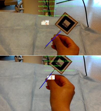
The first method is to transform the virtual needle’s positions from RGBD camera coordinate to positions that are with respect to HoloLens. This approach requires the calibration process between RGBD camera and HoloLens, as described in section 2.3. The advantage of this method is that less computation is required for HoloLens, which improves the smoothness of needle motions because of the relatively weak computational power that HoloLens has. However, the disadvantage is that keeping the marker being visible to both RGBD camera and HoloLens simultaneously could be hard, especially when the HoloLens’s field of view is already narrow. Furthermore, using external camera produces a larger error. This intuitively makes sense, because it combines errors from both the camera tracking and the Camera-HoloLens calibration. This was later proved and could be directly observed in the first image of Figure 7.
The second method is to use HoloLens only and perform all the marker tracking and pivot calibration integration within HoloLens. The advantage of this method is that keeping the marker visible to both is no longer required. Also, the final augmentation is more accurate, as shown in the second image of Figure 7. Surgeons will have more freedom while doing the operation without worrying too much about losing the tracking results. However, the latency is more obvious than the first scheme. Besides the two methods, which provide the basic input positions of the virtual needle, there is another step that must be accomplished to get an ideal displaying result in HoloLens. Unlike augmenting on 2D videos/images, augmenting the virtual objects on physical objects using optical see-through head-mounted displays (OST-HMD) like HoloLens would require an additional calibration. The aim of such calibration is to compute the transformation from world coordinate to HoloLens’s holographic display coordinate so that the virtual objects can be represented in the same coordinate system as the real object. Many researchers have dived into this area and have produced many solutions with respect to accuracy [6, 7], robustness [8, 9, 10], and user friendliness [11, 12]. However, very few of them are aimed for head-mounted displays like HoloLens, which has a holographic display instead of elder monoscopic or stereoscopic displays. The comprehensive approach that is specifically addressing HoloLens’s calibration issue does not exist until Ehsan Azimi, et al. [1] published the completed solution which provides a separate calibration process with output as a ready-to-use 4×4 transformation matrix. By applying this paper’s method, aligning the virtual needle with the real-world physical needle became successful for both tracking schemes. Two figures illustrating results from each scheme is presented below.
Other Augmentation Effects on HoloLens
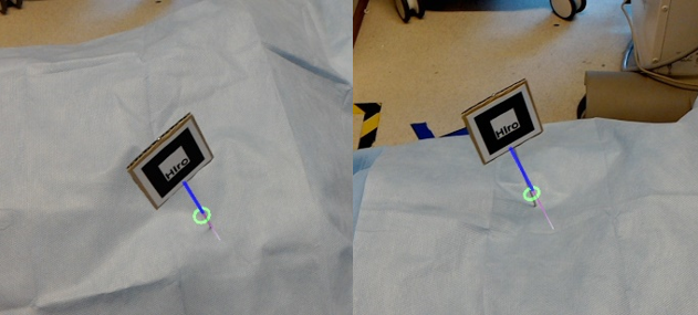
Simple line-model virtual needle augmentation is not enough to guild the surgeon finish the task. Two of the biggest confusing places that surgeons encounter when using head-mounted displays as guidance systems are the insertion position and depth perception. To solve the issue, an invisible laser ray was developed with the starting point same as the needle tip position and the direction same as the needle’s pointing direction. The laser ray, although invisible, collides with the spatial mapping mesh. When such a collision happens, a green ring appears at the collision position with the orientation same as the surface normal. The function is showed in the picture below. This can help the surgeon have a much better understanding of where the needle is going to be inserted. It improves the connection between real world and virtual objects.
When the needle is inserted into the patient’s body, which is detected based on the distance from the entry ring (collision position between the laser ray and surface mesh) to the needle tip, the outside part will remain unchanged as it was before the insertion (blue line). However, the inserted part, which is occluded, is rendered in a distinct way. Example below shows a rendering method using different (thinner) widths and gradient color from dark (pink) to light (white) to increase user’s perception. The rendering method was chosen based on a user-experience survey that will be discussed later in this paper.
Dependencies
describe dependencies and effect on milestones and deliverables if not met
Milestones and Status
- Milestone name: Get familiar with ARToolKit and Unity
- Planned Date: Feb. 24th
- Expected Date: Feb. 24th
- Status: Completed
- Milestone name: Finish camera calibration for Intel RealSense and HoloLens
- Planned Date: Mar. 3rd
- Expected Date: Mar. 3rd
- Status: Completed
- Milestone name: Marker tracking
- Planned Date: Mar. 10th
- Expected Date: Mar. 10th
- Status: Completed
- Milestone name: Skin model detection
- Planned Date: Mar. 24th
- Expected Date: Mar. 24th
- Status: Completed
- Milestone name: Visualize the virtual needle model in Unity
- Planned Date: April. 9th
- Expected Date: April. 9th
- Status: Completed
Reports and presentations
- Project Plan
- Paper Seminar
- Project Checkpoint
- Project Final Presentation
- Project Final Report
Project Bibliography
[1] Long Qian, Ehsan Azimi, Peter Kazanzides and Nassir Navab. Comprehensive Tracker Based Display Calibration for Holographic Optical See-Through Head-Mounted Display. Submitted to 2017 ISMAR
[2] Yamauchi, H., Gumhold, S., Zayer, R., & Seidel, H. (2005). Mesh segmentation driven by Gaussian curvature. The Visual Computer, 21(8-10), 659-668.
[3] R. B. Rusu. Semantic 3D Object Maps for Everyday Manipulation in Human Living Environments. PhD thesis, Computer Science department, Technische Universitaet Muenchen, Germany, October 2009.
[4] Q. Zhan, Y. Liangb, Y. Xiaoa, “Color-based segmentation of point clouds”, Laser Scanning 2009, vol. IAPRS XXXVIII, Sept. 2009.
[5] (n.d.). Microsoft Developer. Spatial mapping. Retrieved from http://developer.microsoft.com/en-us/windows/mixed-reality/spatial_mapping
[6] C. B. Owen, J. Zhou, A. Tang, and F. Xiao. Display-relative calibration for optical see-through head-mounted displays. In Third IEEE and ACM International Symposium on Mixed and Augmented Reality (ISMAR), pages 70–78. IEEE, 2004
[7] M. Tuceryan, Y. Genc, and N. Navab. Single-point active alignment method (SPAAM) for optical see-through HMD calibration for augmented reality. Presence: Teleoperators and Virtual Environments, 11(3):259–276, 2002
[8] E. Azimi, L. Qian, P. Kazanzides, and N. Navab. Robust optical see-through head-mounted display calibration: Taking anisotropic nature of user interaction errors into account. In Virtual Reality (VR). IEEE, 2017.
[9] L. Qian, A. Winkler, B. Fuerst, P. Kazanzides, and N. Navab. Modeling physical structure as additional constraints for stereoscopic optical see-through head-mounted display calibration. In IEEE International Symposium on Mixed and Augmented Reality (ISMAR-Adjunct), pages 154–155. IEEE, 2016.
[10] L. Qian, A. Winkler, B. Fuerst, P. Kazanzides, and N. Navab. Reduction of interaction space in single point active alignment method for optical see-through head-mounted display calibration. In IEEE International Symposium on Mixed and Augmented Reality (ISMAR-Adjunct), pages 156–157. IEEE, 2016
[11] Y. Itoh and G. Klinker. Interaction-free calibration for optical see-through head-mounted displays based on 3d eye localization. In IEEE Symposium on 3D User Interfaces (3DUI), pages 75–82. IEEE, 2014.
[12] Y. Itoh and G. Klinker. Performance and sensitivity analysis of Indica: Interaction-free display calibration for optical see-through head-mounted displays. In IEEE International Symposium on Mixed and Augmented Reality (ISMAR), pages 171–176. IEEE, 2014
[13] Spectator view. (2017). Developer.microsoft.com. Retrieved 14 May 2017, from https://developer.microsoft.com/en-us/windows/mixed-reality/spectator_view
[14] Navab, N., Heining, S., & Traub, J. (2010). Camera Augmented Mobile C-Arm (CAMC): Calibration, Accuracy Study, and Clinical Applications. IEEE Transactions On Medical Imaging, 29(7), 1412-1423. http://dx.doi.org/10.1109/tmi.2009.2021947
