Table of Contents
Photoacoustic System for Spinal Surgery
Last updated: 5/11 2:20 am
Summary
The goal of this project is do conduct proof of concept experiments with a photoacoustic surgical drill prototype. The photoacoustic surgical system is intended for use in spinal surgeries, as a replacement for fluoroscopy.
- Students: Blackberrie Eddins
- Mentor(s): Muyinatu Bell
Background, Specific Aims, and Significance
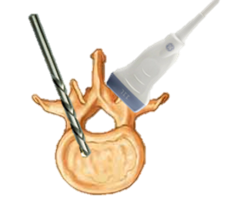
In the U.S. 150,000 spinal fusion surgeries are performed annually. These require the accurate placement of pedicle screws in the affected vertebrae. The current standard of care is to guide screw placement using fluoroscopic images. Many images must be taken throughout the procedure to prevent breaching the bone, which gives a high dose of radiation to both the surgeon and patient. Our proposed solution is to guide drilling with a photoacoustic system instead. Using a drill with an inset optical fiber and an ultrasound transducer placed on the patient's back, the pedicles can be visualized. Photoacoustic acquisition does not have the danger of exposure to radiation, and also has the potential to visualize arteries and nerves, unlike fluoroscopy.
Project Goals
- Proof of Concept Experiments
- Photoacoustic to CT Image Registration
- Novel Image Processing
Deliverables
- Minimum: (4/8)
- Visualize blood in a photoacoustic image with multiple drill tips
- Create phantom for experiments
- Expected: (4/28)
- Track drill tip as it is inserted into pre-drilled vertebra
- Maximum: (5/12)
- Novel image processing methods
Technical Approach
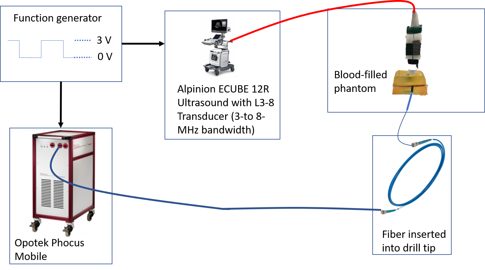
Here is a simplified diagram of how each component in data collection is connected.

The oscilloscope generates waveforms that are sent to the laser and ultrasound system simultaneously. This couples image collection with the generation of a photoacoustic signal from the pulsed laser. The laser is coupled to the drill tip via an optical fiber, which all together creates the drill prototype. The drill prototype is used on the human bone and blood in the phantom to generate relevant surgical data. The ultrasound transducer is held against the phantom to collect the raw data. And finally, this is sent back to the ultrasound system which generates a live display of the system.
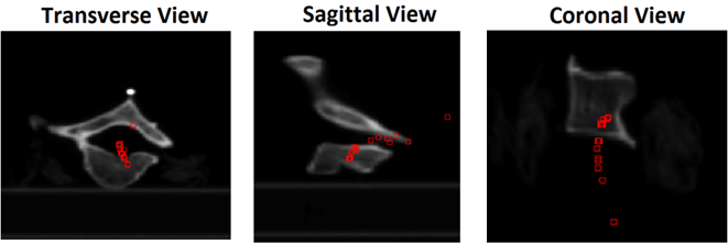
PA images will be taken as each drill tip is inserted into a pre-drilled lumbar vertebra. These will be matched to US images taken with the exact same set-up and the signal change that occurs as the signal passes through the cortical bone into the cancellous bone. The channel data will be exported for processing in order to localize the drill tip in the PA image.
Dependencies
| Dependency | Solution | Progress |
|---|---|---|
| Drill Prototype | use existing | solved |
| Blood | get added to IRB protocol | solved |
| Lab Access | talk to Dr. Bell | solved |
| Experiment Holder for Vertebra | find/design one | solved |
| OPO Laser | maintain one housed in lab | solved |
| MATLAB beam forming scripts | ask grad students | solved |
| vertebra with pre-drilled holes | ask Dr. Bell | have one without blood |
| CT Access/ Training | ask students with access to image for me | solved |
| CT Registration Algorithm | use Eduardo's or other existing | solved |
Milestones and Status
- Phantom Design Finished:
- Planned Date: 2/27
- Expected Date: 2/27
- Status: done
- Begin Experiments:
- Planned Date: 3/03
- Expected Date: 3/03
- Status: finished
- Finish Preliminary Data Collection:
- Planned Date: 3/31
- Expected Date: 4/8
- Status: finished
- Begin Tracking Experiments:
- Planned Date: 4/7
- Expected Date: 4/2
- Status: finished
- Tracking Achieved:
- Planned Date: 4/28
- Expected Date: 5/10
- Status: finished
- Finish All Experiments:
- Planned Date: 5/12
- Expected Date: 5/10
- Status: finished
- Project Presentation:
- Planned Date: 5/11
- Expected Date: 5/11
- Status: presenting
Reports and presentations
- Project Plan
- Project Background Reading
- See Bibliography below for links.
- Project Checkpoint
- Paper Seminar Presentations
- Project Final Presentation
- Final Presentation Teaser
- Project Final Report
Project Bibliography
- Shubert J, Bell MAL, A novel drill design for photoacoustic guided surgeries 2018
- Reiter, A. and Bell, M. A. L., “A machine learning approach to identifying point source locations in photoacoustic data,” in [Photons Plus Ultrasound: Imaging and Sensing 2017], 10064, 100643J, International Society for Optics and Photonics (2017).
- Allman, D., Reiter, A., and Bell, M. A. L., “A machine learning method to identify and remove reflection artifacts in photoacoustic channel data,” in [Ultrasonics Symposium (IUS), 2017 IEEE International], 1–4, IEEE (2017).
- Shubert, J. and Bell, M. A. L., “Photoacoustic based visual servoing of needle tips to improve biopsy on obese patients,” in [2017 IEEE International Ultrasonics Symposium (IUS) ], IEEE (2017)
- Gandhi, N., Allard, M., Kim, S., Kazanzides, P., & Bell, M. A. (2017). Photoacoustic-based approach to surgical guidance performed with and without a da Vinci robot. Journal of Biomedical Optics, 22(12), 1-12. doi:10.1117/1.jbo.22.12.121606
- Rajaee SS, Bae HW, Kanim LE, Delamarter RB. Spinal fusion in the United States: analysis of trends from 1998 to 2008. Spine (Phila Pa 1976). 2012 Jan 1;37(1):67-76. doi: 10.1097/BRS.0b013e31820cccfb. PubMed PMID: 21311399.
- Vidal C, Ilharreborde B, Queinnec S, Mazda K (2016) Role of intraoperative radiographs in the surgical treatment of adolescent idiopathic scoliosis. J Pediatric Orthop 36(2):178–186
- Chen, Carl P. C. M.D. et al. Ultrasound Guidance in Caudal Epidural Needle Placement. Anesthesiology. 101(1):181-184, July 2004.
Other Resources and Project Files
N/A

