Table of Contents
Enabling Technology for Robot Assisted Ultrasound Tomography (Confidential)
Last updated: 05/12/2013 11:30 AM
Summary
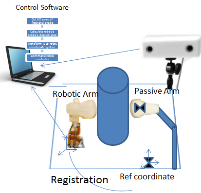
In this project we develop a system which combines a human operated ultrasound probe with a robotic one. The robotic arm (probe) will follow the motion of the human operated probe to place the probes like in a mirror image so that they remain in one line always in respect to translation and rotation. In a way, it is dynamic trajectory tracking. This will help in improving ultrasound quality and finally building a robot assisted ultrasound tomography system.
- Students: Fereshteh Aalamifar, Rishabh Khurana
- Mentor(s): Emad Boctor, Iulian Iordachita, Russell Taylor
Background, Specific Aims, and Significance
The Ultrasound penetration is 10-15 cm maximum. The deeper the tissue, the more attenuation is caused, and consequently, the less quality images can be obtained. This is why ultrasound cannot be used for thick tissues or obese people. In addition since ultrasound waves cannot travel through the air, ultrasound imaging has limitations to be used for computed tomography. In this project, we develop a system which is a combination of human operated probe and a probe attached to a robotic arm. This system can be used to offer higher imaging depth, and to enable ultrasound computed tomography imaging.
Deliverables
- Minimum: (Expected by April 1)
- A robotic arm should follow the position of a mock ultra-sound probe attached to a passive arm, on the other side of a cylindrical phantom, using an optical tracking system
- Expected: (Expected by April 22)
- The mock probes should be replaced with real ones.
- Real data should be collected.
- Study Energy Profile Tracking(EPT) & B-Mode
- Maximum: (Expected by May 6)
- Implement EPT or Bmode and conduct its accuracy study
- Real images shall be collected and reconstructed on a PC to display real-time ultrasound images.
Technical Approach
To develop the system mentioned above, first of all, we will use an optical tracking system to track the human operated probe. This probe’s position is then analyzed on the computer and commands are sent to the robot to move the other probe such that the two probes become aligned. In this project, we use a human operated probe, and an arbitrary cylinder (or a cylindrical phantom) instead of tissue. In addition, in the first phase of the project, we will use mock ultrasound probes.
In the second phase of the project, we will replace the mock probes with real ones and enable the data collection. Since the optical tracking system has the accuracy of more than a millimeter, we will, then, investigate and develop an Energy Profile Tracking (EPT) method to improve the tracking accuracy. The intuition of this method comes from the energy distribution of ultrasound waves. As the energy is not equally distributed in the space. This property can be used to align the probes more accurately by aligning the peaks of EPT. A transmitter and a receiver might be used to enable EPT.
In the third phase, we will implement B-mode and conduct an accuracy study for tracking. Finally, time allowing, we might use reconstruction algorithms to display on screen more interesting real-time images.
Rigid body designs
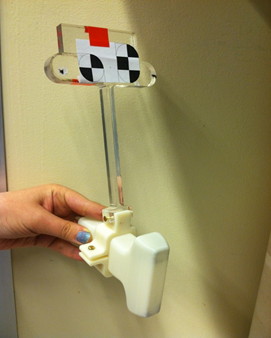
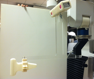
In the first phase we used mock ultrasound probe which were manufactured using 3D printer. Then we designed and manufactured the rigid bodies using laser cutter and 3D printer. Here are the rigid body designs for marker attached to the freehand probe and for microntracker attached to the robot endeffector and robot operated probe.
Ultrasound Calibrations
We require to find the transformation from the marker to the freehand probe image and also from camera to robotic probe image coordinate systems. For the first one, we have done the ultrasound calibration using a sharp pointer. The pointer tip enters the image and the feature is segmented offline to find the location of the pointer tip in the ultrasound image frame. Then tracker reports the position of pointer tip in the camera coordinate system. Then we can find the transformation between the marker and free hand ultrasound image origin using a point to point registration.
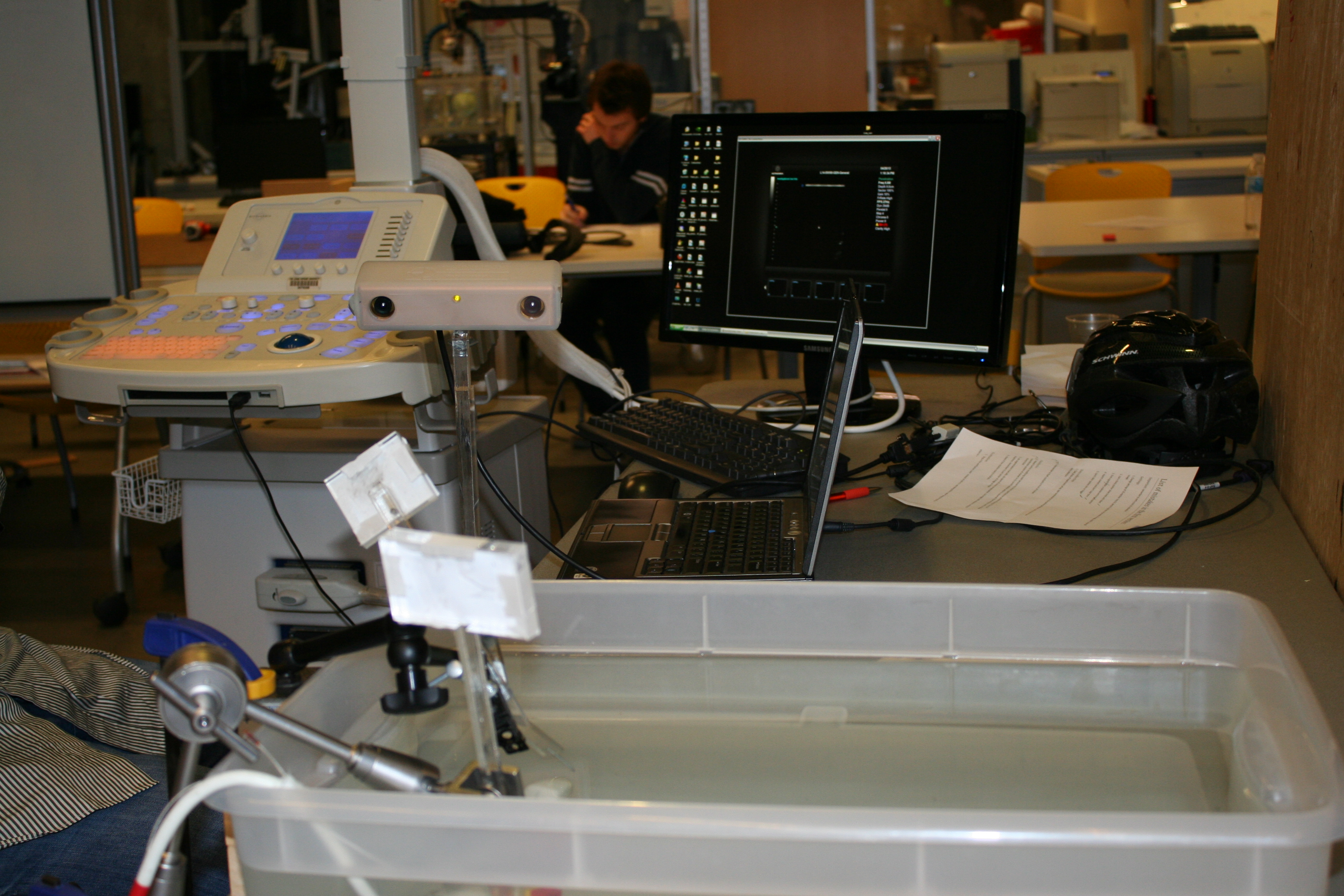
The following image shows the experiment setup to collect data.
Handeye calibration
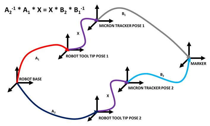
We require to find the transformation from the robot end effector to the camera. This can be done through hand eye calibration and using AX=XB method. The following diagram shows the framework of the experiment to collect data. A marker was rigidly attached and we used cooperative mode of the robot to see the marker from different viewing angles.
Robot
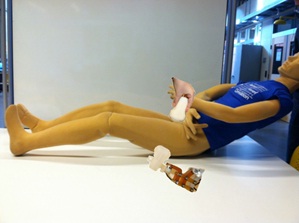
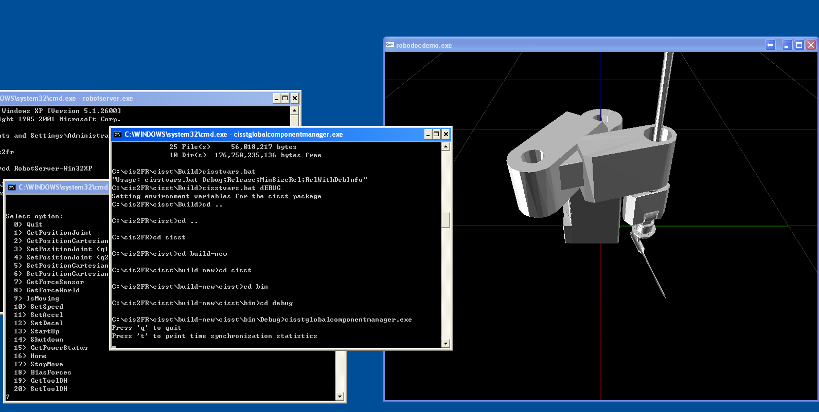
We use robodoc as the robotic arm to hold the probe. We first showed proper functionality of our developed interface using the simulator developed by Min Yang. A screenshot of the simulator can be seen in the following image.
Dependencies
- Robot training by Min Yung (If not met: will have to learn on own)
- Optical Tracker by Dr. Boctor (If not met: can use Dr. Kazanzides's)
- Laptop, Software, Mechanical design and tools by Dr. Iordachita
- Ultrasound Machine and probes by Dr. Boctor (If not met: will delay expected deliverables)
- Unexpected required stuff by Dr. Iordachita and Dr. Boctor internal funds
Milestones and Status
- Milestone name: Optical Tracker
- Planned Date: Mar. 4
- Expected Date: Mar. 18
- Status: Finished
- Milestone name: Robot Training
- Planned Date: Mar. 4
- Expected Date: Apr. 24
- Status: Finished
- Milestone name: Integration and code development
- Planned Date: Mar. 11
- Expected Date: Apr. 3
- Status: Finished
- Milestone name: Experiments and Evaluation( Calibrations and Evaluation)
- Planned Date: Apr. 1
- Expected Date: May 6th
- Status: Finished
- Milestone name: Ultrasound Machine embedding
- Planned Date: Apr. 8
- Expected Date: Apr. 23
- Status: Finished
- Milestone name: EPT & BMode investigation
- Planned Date: Apr. 22
- Expected Date: May 6th
- Status: Finished
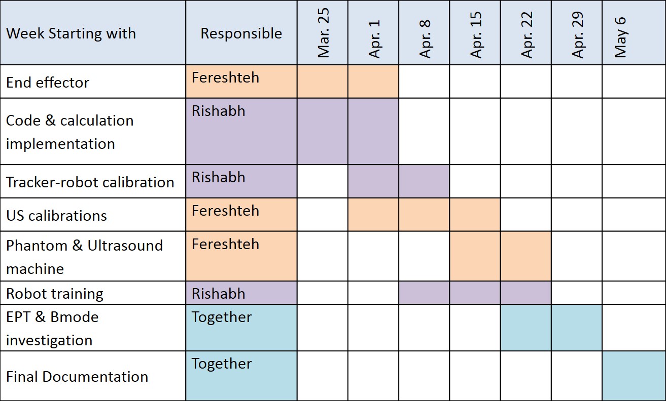
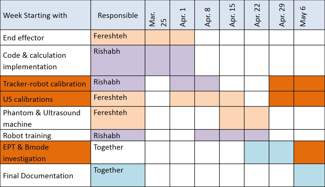
Timeline
Initial Timeline
Updated Timeline at the time of First Checkpoint
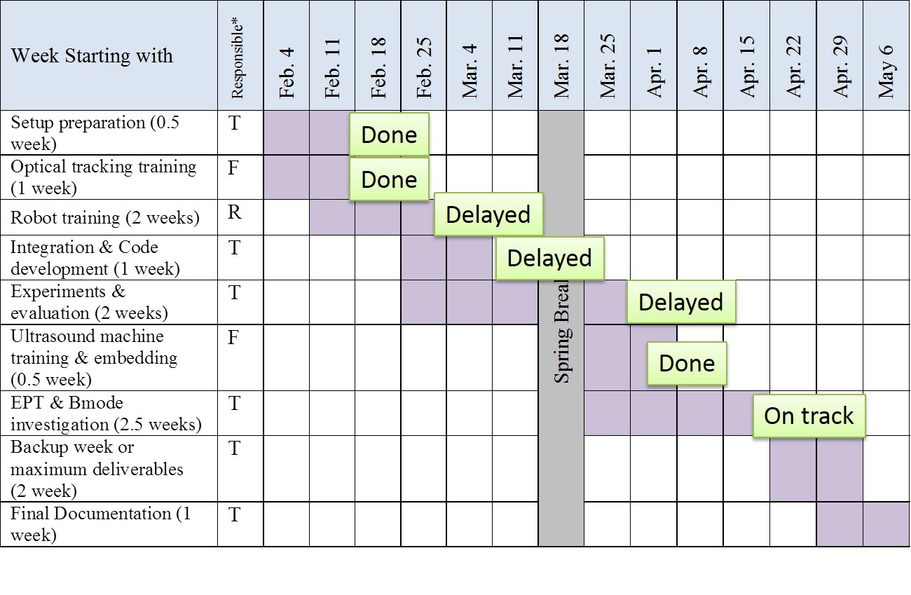
                              Updated Timeline as of Second Checkpoint
                    (The ones in Orange were delayed rest completed on time)
Video of Initial Experiment
Reports and presentations
- links to any appendices or other material
Project Bibliography
- S. E. Salcudean, et. al, “Robot-Assisted Diagnostic Ultrasound – Design and Feasibility Experiments,” Medical Image Computing and Computer-Assisted Intervention – MICCAI’99 Lecture Notes in Computer Science Volume 1679, 1999, pp 1062-1071.
- Purang Abolmaesumi, et. al, “Image-Guided Control of a Robot for Medical Ultrasound,” IEEE Transactions on Robotics and Automation, Vol. 18, No. 1, Feb. 2002, pp. 11-23.
- L. Mercier, T. Lango, F. Lindseth, L. Collins, “A Review of Calibration Techniques for Freehand 3D Ultrasound Systems,” Ultrasound Me. & Biol., Elsevier, Vol. 31, No. 2, pp. 143-165, 2005.
Other Resources and Project Files
THis Package contains all data relevant to the appendix of our report, i.e.
- US_calibration: US calibration tracker data and codes for analysis and verification
- US_data: US images and feature extraction codes
- Markers: markers used for pointer and freehand probe
- Solidworks: final mock probe design, marker and camera placement simulation files, endeffector design files, marker holders files
- EPT(Energy Profile Tracking): Pictures and waveforms, oabserved data, and video for EPT experiment
- RObodocDemoNew : Robot codes, hand-eye calibration accuracy calculation code
