Table of Contents
Co-robotic Ultrasound Imaging
Last updated: April 4th, 2017
Summary
Enter a short narrative description here
- Students: Ting-Yun Fang, Weiqi Wang
- Mentor(s): Haichong K. Zhang, Russel H. Taylor, Emad M. Boctor
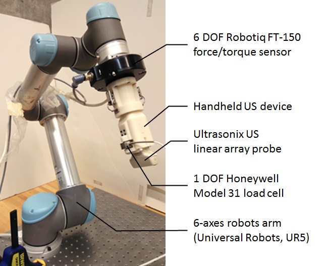
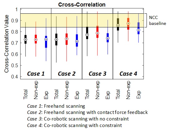
Sonographers commonly suffer from musculoskeletal pain and repetitive strain injuries because the clinical necessity of applying a large force against patients during an ultrasound scanning. Especially when facing obese patients, pregnant women or imaging of deep organs, large contact force is inevitable to find a clear, diagnosable ultrasound image. To overcome this challenge, this project aims to use a cooperatively controlled robotic arm, UR5, to help the operator apply forces and improve the images stability at the same time (Figure 1). Moreover, the robotic system enables the implantation of synthetic tracked aperture ultrasound (STRATUS) imaging, which improves the resolution of ultrasound images (Figure 2).
Background, Specific Aims, and Significance
A paragraph or so here. Give background of the problem. Explicitly state specific aims (numbered list is good) and explain why they are important
Background
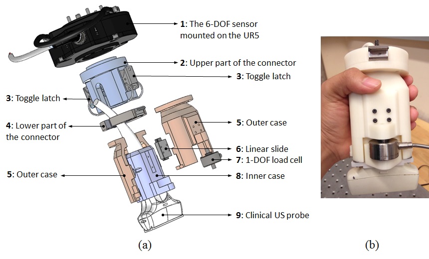
In many clinical situations, sonographers have to apply large force against patients to acquire a clear, diagnosable ultrasound (US) image; especially when facing obese patients, pregnant women, or making deep organs diagnosis. Because of these common demands, sonographers often suffer from musculoskeletal pain and repetitive strain injuries. To overcome this challenge, we are using a robotic arm, to assist the sonographer during the US scanning procedure. This project started in 2015 by Rodolfo Finocchi, Dr. Russ Taylor and Dr. Emad Boctor; I, Ting-Yun Fang, joined the project in 2016 and started with improving the previous control algorithm and mechanical design for an US device (Figure 3). The co-robotic US imaging system is constructed with a robotic arm, UR5, an US machine and probe, a 6 degree-of-freedom (DOF) force sensor and a 1-DOF load cell. The dual force sensors allow the robot to differentiate the force applied by the sonographer and the actual contact force between the US prove and the tissue. Our experiment shows that the co-robotics system can reduce the force applied by the user while improving the US image stability. The co-robotic US system is also used in synthetic tracked aperture ultrasound (STRATUS) Imaging algorithm. STRATUS uses the robotic arm to track and actuate the US probe then transform the US images into a uniform coordinate. By summing up the US signal in the uniform coordinate, the resulting US image has a better resolution and would be beneficial for making diagnosis. This algorithm can be applied to both lateral and elevational direction and has a potential to perform 3D object scanning.
Project Aims
Combining the two valuable features of the co-robotic US imaging system: 1) reduces the force applied by the user and improves the stability of the US images; 2) enables the STARTUS algorithm and increases the image resolution; this project aims to integrate the two applications and makes the system fits better into practical clinical applications. Using cooperative control corresponds with virtual fixtures enables the operator to move the robot and applies STRATUS algorithm on specific region of interests. The virtual fixtures restrain the motion of the robot/user and makes sure the fixed direction of probe motion. The optimum goal would be implementing real time STRATUS that generates US images with better resolution during a scan. Moreover, in order to cover general clinical practices, measuring contact forces between probe and tissue along three directions is inevitable. For example, in the case of echocardiography, the US probe is first pushed against the middle of the chest then orientated to find a preferable view. By replacing the current 1-DOF load cell with a multi axis force sensor, force measurement can be extended to other axes and the robot dexterity can be increased.
Significance Using the co-robotic US imaging system, we want to maximize the use of robot arm. It has potential to assist regarding the US scanning procedures in multiple clinical applications.
Deliverables
- Minimum: (Expected by 3/18)
- Design an IRB protocol for human factor study and human imaging study
- Design an animal (pig) experiment protocol and submit to ACUC for approval
- Design a new probe attachment that is compatible with the convex probe used for the STRATUS algorithm
- Implement virtual fixture features: stay on plane (x and y), stay on line (x and y)
- Integrate STRATUS algorithm with the system (2D in-plane scanning)
- Expected: (Expected by 4/15)
- Ultrasound calibration for the new attachment
- System validation using a phantom (a general US phantom or a female uterus phantom)
- Extended synthetic tracked aperture (SA) from 2D to 3D and perform out-of-plane scanning
- Experiment with the extended SA using a phantom
- Maximum: (Expected by 5/9)
- Design a GUI for real-time interface to visualize collected US data
- Replace the 1-DOF load cell with a multi-axis force sensor for higher dexterity
- Upgrade the current mechanical design of the US probe holder
- Apply one or more of imaging protocol on in vivo subjects
- Implement virtual fixture features: stay at point, follow a trajectory
Technical Approach
here describe the technical approach in sufficient detail so someone can understand what you are trying to do
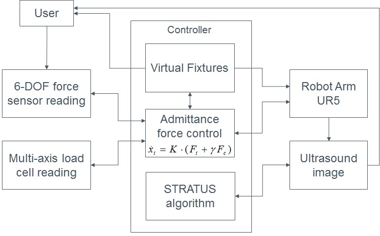
1. Admittance robot control
2. STATUS algorithm
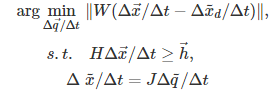
3. Virtual fixtures The general idea of virtual fixture is to solve for delta_q (joint increment) for the linear least square system:
where Δq is the desired incremental motions of the joint variables, Δxd, Δx are the desired and the computed incremental motions of the task variables in Cartesian space, respectively. J is the Jacobean matrix relating task space to joint space. W is a diagonal matrix for weights. We must ensure proper scaling of weights corresponding to different components. Δt is the small time interval of control loop, which is ignored in the algorithm.
There are multiple kinds of geometric constants, the first one we applied is stay at a point, where the robot will maintain a tool position at a desired location.
where ϵ1 is a small positive number that defines the size of the range that can be considered as the target. It implies that the projections of δ p+Δx p on the pencil through Pt be less than ϵ1. We approximate the sphere of radius ϵ1 by polyhedron having n×m vertices, and rewrite the equation by a group of linear inequalities.
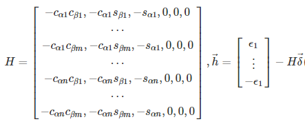
Then we can set H and h as:
Larger values of n and m can reduce the size of the polyhedron, and make it closer to the inscribed sphere.
Most of the virtual fixtures, such as stay on line and stay in plane, have the robot maintain the tool direction, using the constrain:
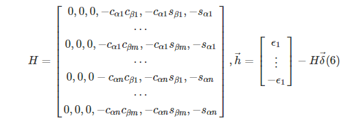
where ϵ2 is a small positive number that defines the size of the range that can be considered as the desired direction. Similar to stay at point, we set H and h as
During ultrasound imaging, a virtual fixture allowing the tool tip to move in a line can improve the imaging quality of STATUS. To guide the tool to move along a reference line, the user must provide the reference line. The default options include moving along the X tool axis and Y tool axis. The linear system has to satisfy the inequality:
Where up is the projection of vector δ p+Δxp on the plane which is perpendicular to line L, and ϵ3 is a small positive number that defines the distance error tolerance to the reference line. A rotation matrix is generated to determine up by generating two unit vectors v1 and v2 that spacn the plane, and defining an arbitary vector l:
Using the information of the plane, we can re write the inequality as
And the H and h matrices will be:
To confine the tool in a given plane, the system must satisfy the inequality:
where ϵ5 is a small positive number, which defines the range of error tolerance. Then H and h are set as
The values of ϵi,i=1,⋯,5 define the range of the error tolerance. They specify how much the robot can drift away from the reference constraints.
Dependencies
describe dependencies and effect on milestones and deliverables if not met
- Robot arm, UR5 – provided by mentor
- Ultrasound machine and probe, Ultrasonix – provided by mentor
- Code for STRATUS algorithm – provided by mentor
- Animal/human experiment – ACUC approved, IRB submitting
- A multi-axis load cell – provided by mentor
- Access to the lab – acquired
- Training and access to machine shop – acquired
Milestones and Status
- Milestone name: Implement virtual fixture: stay on line, stay on plane
- Planned Date: 2/28/2017
- Expected Date: 2/28/2017
- Status: Completed
- Milestone name: Built US probe attachment for convex probe
- Planned Date: 3/14/2017
- Expected Date: 3/14/2017
- Status: Completed
- Milestone name: Connect US machine to Matlab and develop data acquisition program
- Planned Date: 3/20/2017
- Expected Date: 3/20/2017
- Status: Completed
- Milestone name: Integrate 2D STRATUS algorithm
- Planned Date: 3/26/2017
- Expected Date: 3/26/2017
- Status: Completed
- Milestone name: Design and submid animal protocol / IRB protocol
- Planned Date: 3/28/2017
- Expected Date: 3/28/2017
- Status: Completed
- Milestone name: US convex attachment calibration
- Planned Date: 4/5/2017
- Expected Date: 3/20/2017
- Status: Completed
- Milestone name: Validate 2D STRATUS using general phantom
- Planned Date: 4/6/2017
- Expected Date: 4/1/2017
- Status: Completed
- Status: Completed
- Milestone name: Integrate 3D STRATUS algorithm
- Planned Date: 4/16/2017
- Expected Date: xxx
- Status: Working on it
- Milestone name: Validate 3D STRATUS using general phantom
- Planned Date: 4/18/2017
- Expected Date: xxx
- Status: Working on it
- Milestone name: Find and purchase tri-axis load cell
- Planned Date: 4/20/2017
- Expected Date: 3/15/2017
- Status: Completed
- Milestone name: Develop real-time GUI interface to visualize STRATUS
- Planned Date: 5/2/2017
- Expected Date: xxx
- Status: xxx
- Milestone name: Design and built new US attachment for tri-axis load cell
- Planned Date: 5/9/2017
- Expected Date: 3/20/2017
- Status: Complete
- Milestone name: Apply animal protocol on in vivo subjects
- Planned Date: 5/9/2017
- Expected Date: 3/20/2017
- Status: Complete
- Milestone name: Apply IRB protocol on in vivo subjects
- Planned Date: 5/9/2017
- Expected Date: xxx
- Status: xxx
- Milestone name: Implement virtual fixture: stay at point, follow a trajectory
- Planned Date: 5/9/2017
- Expected Date: xxx
- Status: xxx
Reports and presentations
- Project Plan
- Project Background Reading
- See Bibliography below for links.
- Project Checkpoint
- Paper Seminar Presentations
- here provide links to all seminar presentations
- Papers:
- Project Final Presentation
- Project Final Report
Project Bibliography
- Hennersperger C, Fuerst B, Virga S, Zettinig O, Frisch B, Neff T, Navab N (2016) Towards MRI-Based Autonomous Robotic US Acquisitions: A First Feasibility Study. IEEE Transactions on Medical Imaging 1–1. doi: 10.1109/tmi.2016.2620723
- Şen HT, Cheng A, Ding K, Boctor E, Wong J, Iordachita I, Kazanzides P (2016) Cooperative Control with Ultrasound Guidance for Radiation Therapy. Frontiers in Robotics and AI. doi: 10.3389/frobt.2016.00049
- Zhang HK, Cheng A, Bottenus N, Guo X, Trahey GE, Boctor EM (2016) Synthetic tracked aperture ultrasound imaging: design, simulation, and experimental evaluation. Journal of Medical Imaging 3:027001. doi: 10.1117/1.jmi.3.2.027001
- Fang T-Y, Zhang HK, Finocchi R, Taylor RH, Boctor EM (2017) Force-assisted ultrasound imaging system through dual force sensing and admittance robot control. International Journal of Computer Assisted Radiology and Surgery. doi: 10.1007/s11548-017-1566-9
- Li M, Kapoor A, Taylor R (2005) A constrained optimization approach to virtual fixtures. 2005 IEEE/RSJ International Conference on Intelligent Robots and Systems. doi: 10.1109/iros.2005.1545420
- Şen HT, Bell MAL, Iordachita I, Wong J, Kazanzides P (2013) A cooperatively controlled robot for ultrasound monitoring of radiation therapy. 2013 IEEE/RSJ International Conference on Intelligent Robots and Systems. doi: 10.1109/iros.2013.6696791
- Şen HT, Cheng A, Ding K, Boctor E, Wong J, Iordachita I, Kazanzides P (2016) Cooperative Control with Ultrasound Guidance for Radiation Therapy. Frontiers in Robotics and AI. doi: 10.3389/frobt.2016.00049
- Zhang HK, Finocchi R, Apkarian K, Boctor EM (2016) Co-robotic synthetic tracked aperture ultrasound imaging with cross-correlation based dynamic error compensation and virtual fixture control. 2016 IEEE International Ultrasonics Symposium (IUS). doi: 10.1109/ultsym.2016.7728522
- Gilbertson MW, Anthony BW (2013) An ergonomic, instrumented ultrasound probe for 6-axis force/torque measurement. 2013 35th Annual International Conference of the IEEE Engineering in Medicine and Biology Society (EMBC). doi: 10.1109/embc.2013.6609457
Other Resources and Project Files
Here give list of other project files (e.g., source code) associated with the project. If these are online give a link to an appropriate external repository or to uploaded media files under this name space.
