Table of Contents
Anatomical Mesh-Based Virtual Fixtures for Surgical Robots
Last updated: 4:30 pm, May. 9, 2020
NOTE: My project was redirected mid-semester. The previous project was “Towards Robust Vision Based SLAM System in Endoscopy with Learning Based Descriptor”, and its page can be found here
Summary
Enter a short narrative description here
- Student: Yiping Zheng
- Mentor(s): Zhaoshuo Li, Russell Taylor
- Goal: Improving the robustness of the virtual fixture algorithm and related software. Creating a motion planning demo for Galen robot to perform robot-assisted mastoidectomy task, which compromised to creating a demo in simulation due to COVID-19.
Background, Specific Aims, and Significance
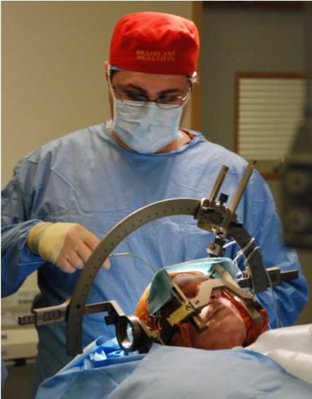
Mastoidecotmy is a deliberate surgical procedure which is important to the treatment of diseases such as cochlear implant, acoustic neuroma etc. Surgeons have to mechanically drill a hole on patient's skull and all the way down to the meningeal, meanwhile carefully avoiding sensitive anatomy structure such as facial nurve, sigmoid sinus, and arteries. The drilling process is a challenging process to surgeons which often lasts 8 hours.
Surgical robots such as da Vinci Surgical System can mitigate the challenges by extending human capabilities. However, mainly because of the precision requirement of mastoidectomy is very high, so far there hasn't been any application or attempt of robot assisted mastoidectomy to our best knowledge.
Virtual fixture is software motion constraints, can further reduce the operational difficulties by allowing the surgeon and robot to work together to complete the surgical task with improved stability, reliability and precision. By tracking the relative position of the surgical tool with regard to patients body, it can stop the surgeon from making sudden motions and accidentally damaging critical anatomies and have the potentiality to make the robot assisted mastoidectomy possible.
Recently, a new virtual fixture generation algorithm was proposed which fits the scenario of mastoidectomy very well. By obtaining the 3D data of patient's skull, either pre-operatively via CT scan or intra-operatively via 3D ultrasound, it can generate virtual fixtures online from polygon mesh representations of complex anatomical structures and provide dynamic constraint formulation for the planning algorithm. The algorithm has been testified through validation and runtime experiments.
In this project, I'm going to integrate this anatomical virtual fixture generation algorithm with Galen surgical robot and perform a demo of robot-assisted mastoidectomy, which may be very useful to avoid touching patient's critical anatomy structure and mitigate surgeons' tension in the procedure.
Deliverables
Here we kept 2 versions of deliveralbes, idealistically original plan A and relistically revised plan B.
A. Original Plan
- Minimum: (Expected by Mar. 10, 2020)
- Simple geometry code integration
- Expected: (Expected by Apr. 17, 2020)
- Patient anatomy code integration(3D phantom)
- Maximum: (Expected by May. 1, 2020)
- Complete the user study.
B. Revised Plan under 2019-nCov
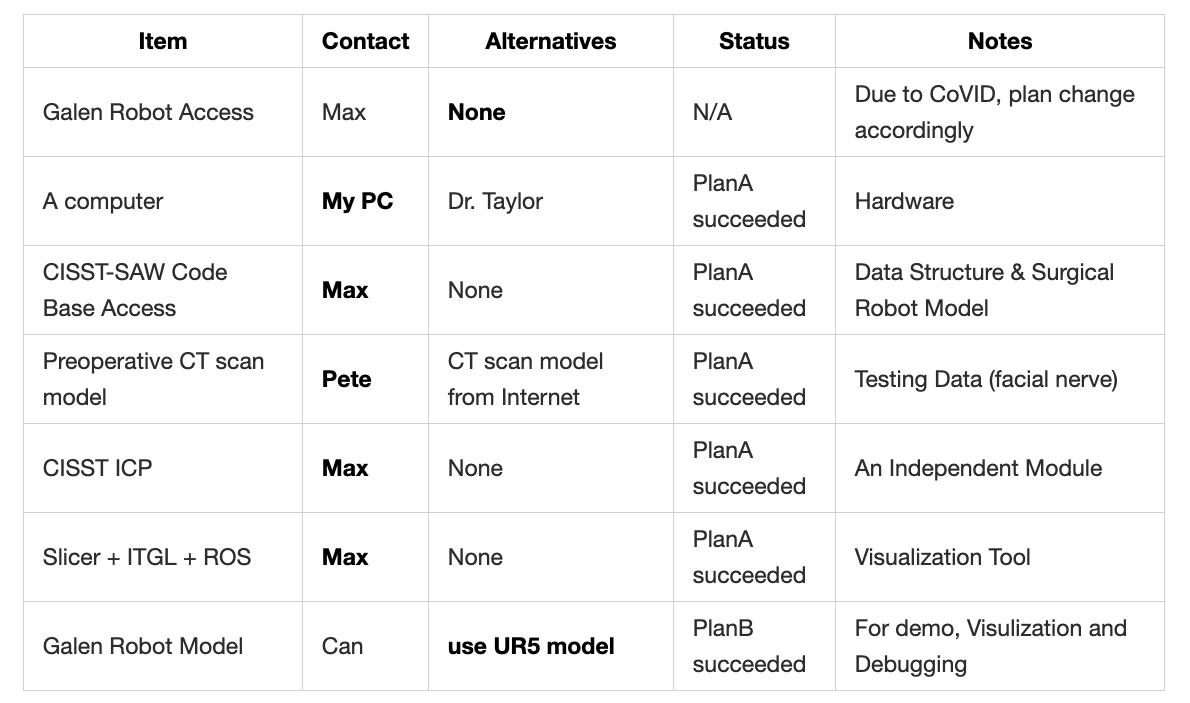
Since the laboratory access is not achievable any more, the goal for the CIS2 project has been shifted to simulation environment accordingly, and improving its robustness, rather than creating a demo in real world.
- Minimum: (Expected by Mar. 10, 2020)
- Get slack formulation integrated into the optimal controller.
- Expected: (Expected by Apr. 17, 2020)
- Perform the surgery task simulation with a simple robot model, with respect to the whole surface of the end-effector.
- Maximum: (Expected by May. 1, 2020)
- Perform the surgery task simulation with the Galen robot model, with respect to the complexity of its forward kinematics and Jacobian.
Technical Approach
Since our goal is to follow the new algorithm proposed in [1], create a demo based on it and possibly improve its performance. So in Part A~C of the approach section, the approach of [1] will be presented again and followed with some algorithmic improvement of my own, which is in Part D~G.
A. Constraint Optimization
Constraint optimization approaches are well-established methods to implement virtual fixtures. In this project, we formulate robot kinematic motion control as a quadratic optimization problem with linear constraints. Objective function solved for the desired motion:
where ∆x and ∆x_d are the computed and desired incremental Cartesian positions, and ∆q is the incremental joint position. J is the Jacobian matrix relating the joint space to the Cartesian space. A and b are matrix and vectors necessary to describe the linear constraints.
In a telemanipulated control environment, ∆x in the objective function is computed from the motion of the master manipulator. Additional objectives may be added to express additional desired behaviors. Otherwise, in cooperative control setting, ∆x is computed from the force sensor input.
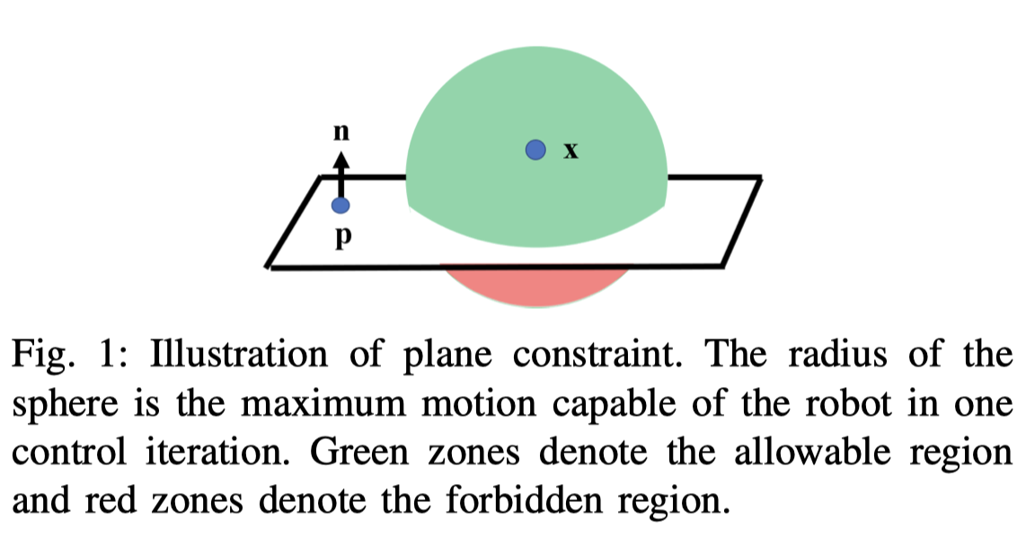
Inequality constraints can be used to impose motion constraints. For example, a virtual forbidden wall for tool tip x can be defined by a hyper-plane with normal n and point p , i.e. tool tip can only move on the positive side of the hyperplane as shown in Fig. 1. This can be achieved by forcing the signed distance d_t from the tool tip to plane at any time t to be positive, i.e.,
where ∆d is the change of the signed distance. The constrained motion can be realized by setting A = n and b =-n^T (x-p). The constrained least-squares problem may then be solved to produce the desired motion. Additional terms may be added to further constrain the tool motion.
B. Polygon Mesh
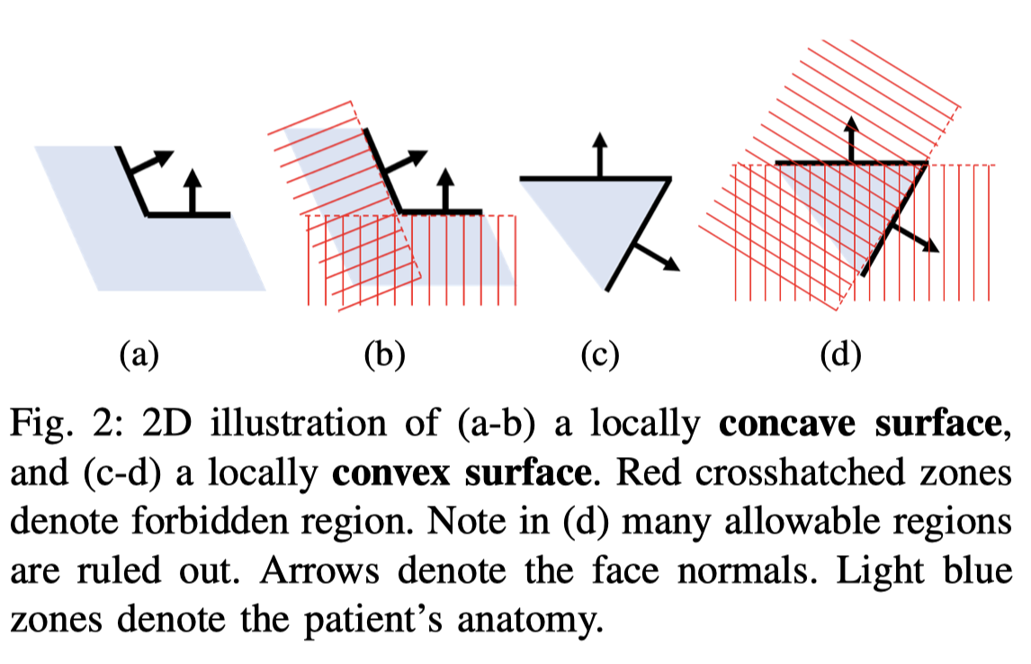
In this work, polygon meshes consisting of triangles are used to represent anatomical surfaces. A locally concave surface (Fig. 2a) produces a convex set of linear constraints. It is safe to include all triangles as plane constraints (Fig. 2b). A locally convex surface (Fig. 2c) produces a non-convex set of linear constraints. Naively adding all triangles as plane constraints will rule out many allowable regions (Fig. 2d). This necessitates an approach to dynamically activate and deactivate the constraints based on the local convexity and concavity of the anatomical surfaces.
C.Polygon Mesh Constraint Alogrithm
Instead of considering the whole mesh object, a motion sphere is built around the current position with the radius defined by the maximum motion capable of the robot in one control iteration (shown as the sphere in Fig. 1). The triangles intersected by the motion sphere are the only necessary ones to be considered in the current iteration. To enable efficient geometric-search intersection, the anatomical mesh is stored as a Principle Direction Tree (PD-Tree) [14]. The PD-Tree is similar to the KD-Tree, but with nodes split along the maximum distributive direction of the data. This provides an additional boost in search efficiency especially when triangles are not uniformly distributed. During the PD-Tree construction, the adjacency information of the triangles is stored. Using the PD-Tree of the anatomy and the motion sphere of the tool position, the corresponding closest points CP and face normals N of each intersected triangle are returned.
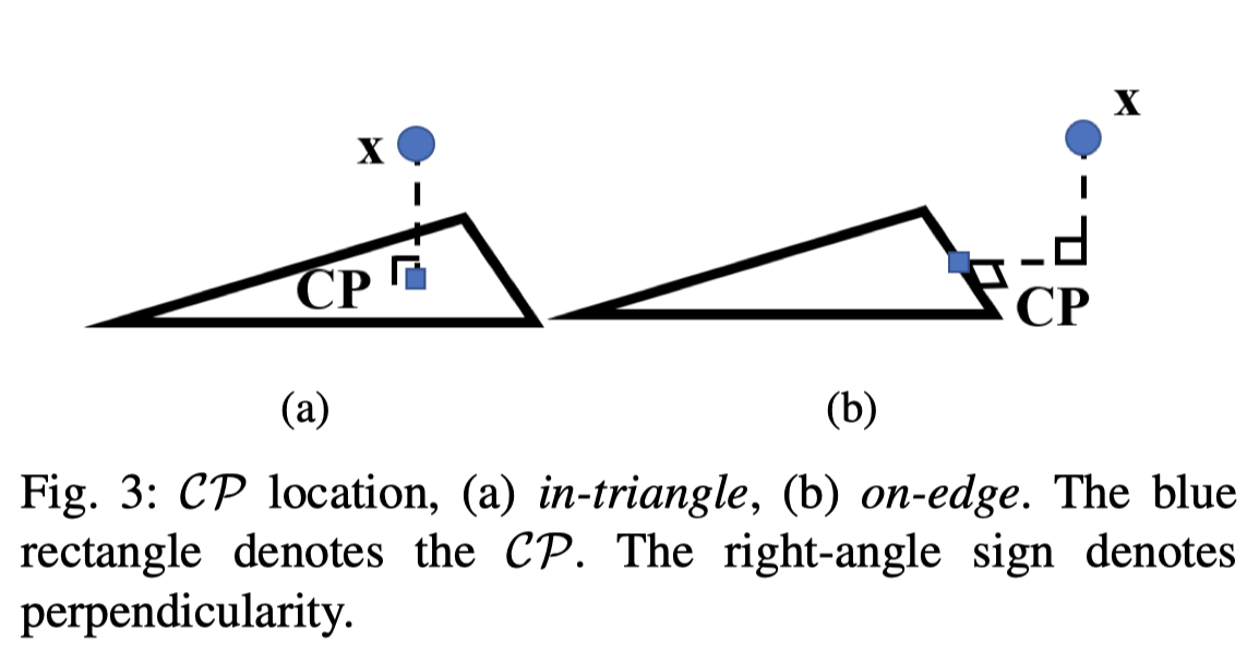
The closest point location on a triangle is found using [15], which can land in two places - in-triangle or on-edge (Fig. 3). The closest points on each triangle are necessary to determine the local convexity/concavity and approximate local geometries using plane constraints. Based on the CP location, there are only three cases for a given triangle Ti to be added to the list of active constraints L.
The three cases of local geometry and the completeness of the algorithm is discussed in detail in [1]. In general, based on the local information of two surface normals, two closest points, and the point of the tool tip, we can use the proposed algorithm to select the active constraints efficiently and completely.
D. Extending the tool tip point to a sphere. (Tool Radius Constant)
Above we assumed that the tool tip is a geometric point, this holds true for the sharpness of most of the surgical tools, but this isn't inclusive. There exists some surgical tools with blunt tip. Therefore, with regard to generality and compatibilty, it'll be better to use a sphere to model the shape of the tool tip, since with the sphere model, we can have a radius variable to adjust to the sharpness of the tool tip. This can be achieved through modifying formula 2 as follows.
We need to change the code implementation to add the sphere model feature.
E. Adding Slack Variable
During the surgery, surgeons sometimes need to violate some virtual fixture constraints of the patient's tissue in order to perform cutting or drilling operation. In order to implement this, we nee to set a slack variable for every active constraint to represent to what extent it can be violated. If some certain virtual fixture constraints are violated in the current planning-and-moving iteration, it should be recorded and automatically added to the next iteration as active constraints, since it might not be recognized as active constraints by the active-constraint-selection algorithm.
F. Tool Shaft Sampling
Currently, we've only considered the tool tip, either modeling it as a point or a sphere. However, practically, the whole tool shaft should all be considered in the motion planning algorithm. Based on the current point-based algorithm, we propose a sampling based method by which the current algorithm can be extended to the scope of the whole tool shaft.
We plan to generate some points evenly distributed in the region of the tool shaft and generate a sphere at each sample points. The radius of each sphere can be adjusted to finely fit the shape of the tool shaft. But for validation, we will only consider the simplest case, model the tool shaft as a cylinder. We will attach 3 rotation variables to the state x, making it 6-Dof. We'll have to adjust the Jacobian matrix accordingly, and modify the construction of the constraint matrix, enabling it to take all the active constraints of all the sample points, with regard to 6 state variables.
The intermediate distance of sample points is deliberately chosen to be 0.88*sphere_radius so that the sampling density is optimally balanced between the sampling efficiency and the gap between two sample spheres.
G. Automatic Tool Retraction
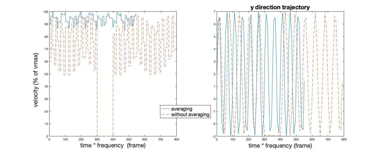
In many surgical navigation scenario, when surgeons have inserted a tool into patient's body, the retraction process can be automated by following the same path and can be accelerated by interpolating and smoothing the 1st order of insertion trajectory. This automatic tool retraction feature can save surgeons some energy and shorten the overall surgery time. This idea is implemented by first recording the insertion trajectory, interpolating intermediate points with various density according to the time stamp of the recorded trajectory points, and reversing the whole sequence, playing from end to the beginning.
Following is the position and velocity trajectory of the retraction process, compared to that of the insertion process.
Dependencies
Milestones and Status
Below two versions of steps and milestones are kept. One original version, representing the idealistic plan. One revised version, representing the compromised plan due to 2019-nCov situation.
Original Plan
Phase 1: Getting Started, Mar.5 ~ Mar.19 (14 days)
- Milestone name: Loading function for mesh STL binary file.
- Planned Date: Mar.19
- Expected Date: Mar.19
- Status: \
Phase 2: Implement the Algorithm, Mar.20 ~ Apr. 5 (14 days)
- Milestone name: Passing compilation of the integrated cotroller
- Planned Date: Apr.5
- Expected Date: Apr.5
- Status: \
Phase 3: Test the controller with simple robot model, Apr.6 ~ Apr.20 (14 days)
- Milestone name: A video demo of a simple robot that can actually perform the above tasks
- Planned Date: Apr. 20
- Expected Date: Apr. 20
- Status: \
Phase 4: Test the controller using Galen robot model, Apr.21 ~ Apr.30 (10 days)
- Milestone name: A video demo of the Galen robot that can actually perform the above tasks
- Planned Date: Apr. 20
- Expected Date: Apr. 20
- Status: \
Revised Plan
Phase 1: Getting Started, Mar.5 ~ Mar.19 (14 days)
- Write proposal, give presentation and construct the wiki page.
- Get familiar with the CISST code base (focused on cisstNumerical, and the SAW Constraint Controller part)
- Milestone name: Loading function for mesh STL binary file.
- Planned Date: Mar.19
- Expected Date: Mar.19
- Status: 100%
Phase 2: Implement the Algorithm, Mar.20 ~ Apr. 5 (14 days)
- Get familiar with the cisstICP
- Adding slack variable of soft constraints to the optimal controller. (This is also the minimum deliverable)
- Milestone name: Passing compilation of the integrated cotroller
- Planned Date: Apr.5
- Expected Date: Apr.5
- Status: 100%
Phase 3: Test the controller with simple robot model, Apr.6 ~ Apr.20 (14 days)
- Test the controller with a simple robot model (eg. UR5 robot arm)
- Test the controller with 3-Dof translation-only motion.
- Test the controller with simple geometry obstacle.
- Test the controller with 3D phantom of patient anatomy. (online data source)
- Improving the mesh-constraint algorithm with respect to the whole surface (use sphere model) of the end-effector, rather than modeling it with a point. (This is also the expected deliverable)
- Test the controller with 6-Dof motion.
- Milestone name: A video demo of a simple robot that can actually perform the above tasks
- Planned Date: Apr. 20
- Expected Date: Apr. 20
- Status: 10%
Phase 4: Test the controller using Galen robot model, Apr.21 ~ Apr.30 (10 days)
- Integrating the tested controller into the Galen Robot code base.
- Test all the above tasks with respect to the Galen Robot's forward kinematics and Jacobian matrices.
- Milestone name: A video demo of the Galen robot that can actually perform the above tasks
- Planned Date: Apr. 20
- Expected Date: Apr. 20
- Status: 0%
Reports and presentations
- Project Plan
- Project Background Reading
- See Bibliography below for links.
- Project Checkpoint
- Paper Seminar Presentations
- Project Final Presentation
- Project Final Report
- links to any appendices or other material
- Research Log
Project Bibliography
* here list references and reading material 1. Zhaoshuo Li et al. Anatomical Mesh-Based Virtual Fixtures for Surgical Robots (unpublished by Mar. 2020)
2. Funda, J., Taylor, R. H., Eldridge, B., Gomory, S., & Gruben, K. G. (1996). Constrained Cartesian Motion Control for Teleoperated Surgical Robots. Robotics, 12(3).
3. Xia, T., Kapoor, A., Kazanzides, P., & Taylor, R. (2011). A constrained optimization approach to virtual fixtures for multi-robot collaborative teleoperation. IEEE International Conference on Intelligent Robots and Systems, 639–644. https://doi.org/10.1109/IROS.2011.6048816
4. Li, M., Ishii, M., & Taylor, R. H. (2007). Spatial Motion Constraints Using Virtual Fixtures Generated by Anatomy. 23(1), 4–19.
5. Kapoor, A. (2008). Motion constrained control of robots for dexterous surgical tasks.
6. S. A. Bowyer, B. L. Davies and F. Rodriguez y Baena, “Active Constraints/Virtual Fixtures: A Survey,” in IEEE Transactions on Robotics, vol. 30, no. 1, pp. 138-157, Feb. 2014, doi: 10.1109/TRO.2013.2283410.
7. Masotidectomy Video https://www.youtube.com/watch?v=jnonLwxW2Cg
8. 3D Slicer Simulation Environment Tutorial https://rosmed.github.io/ismr2019/prerequisite
9. CISST-SAW Code Base https://github.com/jhu-cisst/cisst/wiki
10. cisstICP Code Base https://git.lcsr.jhu.edu/zli122/cisstICP
11. VF guided skull cutting using ultrasonic cutter and dVRK https://github.com/mli0603/PolygonMeshVirtualFixture
12. Galen Model Base https://bitbucket.org/GalenRobotics/researchrepo/src/master/source/robot/
13. STL reader https://github.com/sreiter/stl_reader
14. STL parser http://www.dillonbhuff.com/?p=5
Other Resources and Project Files
Here give list of other project files (e.g., source code) associated with the project. If these are online give a link to an appropriate external repository or to uploaded media files under this name space (456-2020-07).
