Table of Contents
Robot-Assisted Transcranial Magnetic Stimulation (RA-TMS)
Last updated: 5/11/2018, 12:27 AM
Summary
Our objective is to assess subjective visual vertical (SVV) perception via eye tracking and the relationship between SVV and the supramarginal gyrus (SMGp). To accomplish this, there is a need to create a robotic tool that can perform transcranial magnetic stimulation (TMS) automatically to measure areas of activity around the brain. This project will focus on the implementation of such a system both in simulation and with a physical robot.
- Student: Ganesh Arvapalli
- Mentor(s): VOR lab: Dr. Amir Kheradmand, Dr. David S. Zee, BIGSS lab: Farshid Alambeigi, Dr. Mehran Armand
Background:
Spatial orientation and navigation are highly dependent on vestibular inputs alongside visual information. Vestibular input integration appears to be linked to regions in the right hemisphere of the brain, including the superior temporal gyrus and the inferior parietal lobule. One specific area of the latter, the supramarginal gyrus (SMGp) has been studied regarding its relationship to vestibular feedback through functional neuroimaging studies and behavior analysis following cortical lesions in the area. However, not all functional roles in the aforementioned regions are known nor how information is processed in and between these areas. To assess the impact of changes in these regions, a test called the subjective visual vertical (SVV) is employed. SVV testing involves a subject identifying what they consider to be perpendicular to the ground (“earth vertical”). This vertical normally very stable, known as “orientation constancy,” but can be affected by the vestibular system, proprioception (determining relative head and body positions), and vision. Acknowledging this as the case, the activation or inhibition of related cortical regions is currently being explored to induce a measurable impact on vestibular feedback. One approach is transcranial magnetic stimulation (TMS), in which magnetic fields are induced in targeted area, thereby stimulating or inhibiting parts of the brain. The specific method used in this study was continuous theta burst stimulation (cTBS), which is designed to decrease cortical activity. Thus, TMS was used to mimic lesions in the SMGp and the effects of its inhibition were investigated with regards to impact on the SVV.
Specific Aims:
It has been well established that TMS can be used for the inhibition of cortical brain activity for a variety of experimental setups. However, this can be a labor-intensive process due to the constant repositioning necessary to move the TMS applicator coil to target areas with the correct orientation. In addition, the potential for experimenters to make mistakes in positioning the coil could lead to erroneous application of non-target sites. Above this, there is no method of visualization once results have been found to localize activity to specific areas. Therefore, there is a need to automate TMS application for specified regions of the brain using a robotic tool so that mapping brain activity can be simplified. This project worked on one implementation that included a force feedback component to prevent TMS application from causing injury to subjects.
Significance:
The process of TMS application over a grid area on the cortex of the brain has been shown to be difficult to automate, but the steps taken by this project demonstrate its practicality. Although we were specifically studying the SMGp, there is evidence to suggest that other regions of the brain could be investigated in the same fashion. We successfully managed to achieve the original minimum deliverables and the adjusted expected deliverables. The maximum deliverables unfortunately required additional time to achieve due to the investment made into printing the custom tool holder. However, all components are now in place for the maximum goals to be achieved with approximately 2 more months of work. It is still necessary to gain approval from the necessary review boards as to whether the automatic procedure is safe enough to use for other experiments. Also, the procedure will have to be fine tuned to adjust the weighting parameters for the soft constraints and to find the maximum allowable forces. Future plans for this project would include attempting to keep the orientation of the coil constant relative to the individual's head and to improve the force feedback. Tangency to the subject's head will also be a difficult issue to resolve, but given the code and parts made by this project, it is certainly possible.
Deliverables
- Minimum: (4/12/18)
- Develop control algorithms to move the TMS coil in simulation reliably between given points (no safety concerns, linear motion only).
- Documentation of control algorithms and motion planning
- Expected: (4/26/18)
- Add constraints to robot path planning to ensure patient safety with force feedback
- Create custom tool holder for TMS coil in conjunction with six-axis force sensor and robot
- Documentation of safety constraint code and motion adjustments
- Maximum: (5/10/18)
- Move the TMS coil reliably between many head locations on the physical robotic system
- Document implementation in full robotic system, including installation instructions
Technical Approach
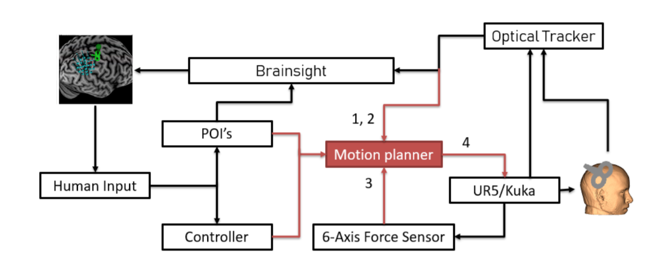
 A flowchart diagram of our approach is presented in the above figure. Our goal was to implement the arrows in red, constructing a motion planner capable of directing movement of the coil to various points of interest (POI's). To walk through the process, we start with human input for coordinates where POI's should be located, based on brain scam imagery. To visualize the brain scan and the cortex of the subject, a software called Brainsight was used. The researcher using this tool would also be given a controller with which they could control the location of the coil. The motion planner would take inputs from either defined POI's or controller input and produce motion in either a UR5 or Kuka system. For this project, we decided to focus on a UR5 implementation but a Kuka system could be explored in the future provided the coil is not too heavy. The UR5 would then move the coil to a POI or specified location on the subject's head and provide force feedback information including the torque and pressure applied. This force information would be fed back to the motion planner which would reduce pressure by moving away from the subject if necessary. Above all components would be an optical tracker recording positions of the subject, the UR5, and the coil, each of which would have tracking markers. The location information would be sent back to Brainsight to help draw the position of the TMS coil over the grid location being measured.
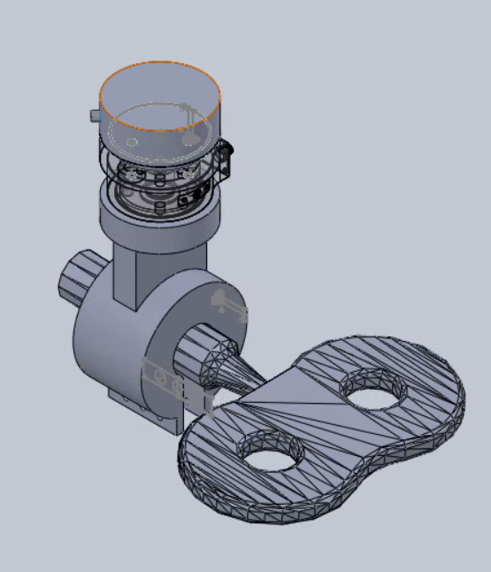
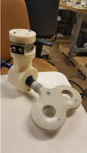
As part of our approach, we decided to develop a custom tool capable of holding the TMS coil in place, parallel to the end effector of the robot. The tool would grip the handle of the coil and place the center of the double loop at the target location. The coil would be held parallel to the cortex of the subject, determined prior to application by MRI scan and 3D reconstruction.
Dependencies
- Lab access: To work in focused environment with simulation software (from Farshid)
- Status: Complete
- Simulation software: Model motion of robot before testing on actual system (from Farshid)
- Status: Complete
- Brain visualization software: Construct 3D model of head based on MRI scans and show tool relative to brain (from Amir)
- Status: Complete
- Defined safety constraints: Ensure tool pressure against head is not dangerous (from Farshid and Amir)
- Status: Will be completed next week once tool is assembled
Milestones and Status
- Recreating experiment environment in simulation without motion
- Planned Date: 3/2
- Expected Date: 3/8
- Status: Complete
- Calculating TMS tool vector to targeted POI’s on scalp in real time
- Planned Date: 4/6
- Expected Date: 4/12
- Status: Complete
- Constraining robotic motion to remain tangent to head (within safety constraints)
- Planned Date: 4/20
- Expected Date: 4/26
- Status: Complete
- Converting simulated motion data into actual robotic movement
- Planned Date: 5/4
- Expected Date: 5/10
- Status: Upcoming
- Documentation reassessment (ongoing for each part)
- Status: Complete
Results
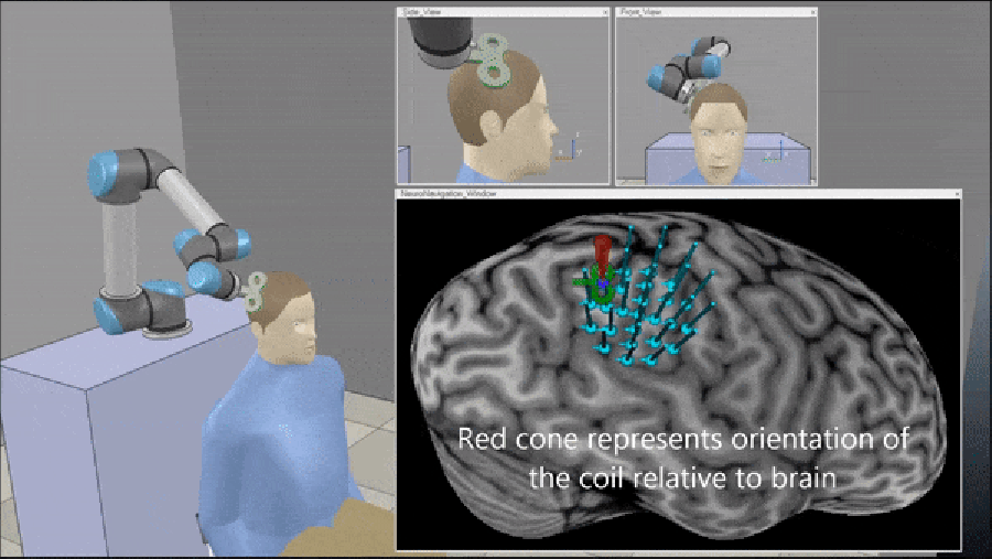
Simulation was accomplished with Slicer, which allowed visualization of the UR5 given a set of joint angles. The path output from the MATLAB solution produced a direct path between specified points with reasonable accuracy. A manual check was able to show that the robot successfully moved linearly along a path in Slicer as well. As can be seen from the figure, the robot was able to converge to the desired location successfully.
To construct the TMS coil holder, we first needed to interface it with the force sensor and then interface the force sensor with the end effector of the UR5. Naturally, we constructed two separate parts that each each connect two others. The first was the connector between the UR5 end effector and the force sensor. The force sensor chosen was the KMS-40 six-axis force sensor which would allow us to make torque measurements in addition to contact forces. We made screw holes in a small disk designed to fit over the holes of the end effector and the holes of the force sensor. The force sensor used M4 screw heads and the UR5 used M8 screw heads. Models for these were found online to construct a validation assembly. For the second part of the coil holder, we needed to attach the force sensor to the coil, but since the coil needed to be kept parallel to the end effector, we needed a way to grip it such that the double loop would stay offset, but parallel to the face of the force sensor. Ultimately, we chose a design where a loop would close around the handle connecting the TMS coil to its cable. The loop could be tightened with screws to adjust the level of grip.
Reports and presentations
- Project Plan
- Project Background Reading
- See Bibliography below for more links.
- Project Checkpoint
- Paper Seminar Presentations
- Project Final Presentation
- Project Final Report
- Bitbucket Repository
Project Bibliography
- Chetana, N., & Jayesh, R. (2015). Subjective Visual Vertical in Various Vestibular Disorders by Using a Simple Bucket Test. Indian Journal of Otolaryngology and Head & Neck Surgery, 67(2), 180–184. https://doi.org/10.1007/s12070-014-0760-0
- Pereira, C. B., Kanashiro, A. K., Maia, F. M., & Barbosa, E. R. (2014). Correlation of impaired subjective visual vertical and postural instability in Parkinson’s disease. Journal of the Neurological Sciences, 346(1–2), 60–65. https://doi.org/10.1016/j.jns.2014.07.057
- Scocco, D. H., Wagner, J. N., Racosta, J., Chade, A., & Gershanik, O. S. (2014). Subjective visual vertical in Pisa syndrome. Parkinsonism & Related Disorders, 20(8), 878–883. https://doi.org/10.1016/j.parkreldis.2014.04.030
- Kheradmand, A., Lasker, A., & Zee, D. S. (2015). Transcranial Magnetic Stimulation (TMS) of the Supramarginal Gyrus: A Window to Perception of Upright. Cerebral Cortex, 25(3), 765–771. https://doi.org/10.1093/cercor/bht267
- Otero-Millan, J., Roberts, D. C., Lasker, A., Zee, D. S., & Kheradmand, A. (2015). Knowing what the brain is seeing in three dimensions: A novel, noninvasive, sensitive, accurate, and low-noise technique for measuring ocular torsion. Journal of Vision, 15(14), 11. https://doi.org/10.1167/15.14.11
- Cárdenas-Morales, L., Nowak, D. A., Kammer, T., Wolf, R. C., & Schönfeldt-Lecuona, C. (2010). Mechanisms and Applications of Theta-burst rTMS on the Human Motor Cortex. Brain Topography, 22(4), 294–306. https://doi.org/10.1007/s10548-009-0084-7
- Brodsky, M. C., & Holmes, J. M. (2012). Torsional augmentation for the treatment of lateropulsion and torticollis in partial ocular tilt reaction. Journal of American Association for Pediatric Ophthalmology and Strabismus, 16(2), 141–144. https://doi.org/10.1016/j.jaapos.2011.11.009
- Gorelick, D. A., Zangen, A., & George, M. S. (2014). Transcranial magnetic stimulation in the treatment of substance addiction: TMS as addiction treatment. Annals of the New York Academy of Sciences, n/a-n/a. https://doi.org/10.1111/nyas.12479
- Narayana, S., Papanicolaou, A. C., McGregor, A., Boop, F. A., & Wheless, J. W. (2015). Clinical Applications of Transcranial Magnetic Stimulation in Pediatric Neurology. Journal of Child Neurology, 30(9), 1111–1124. https://doi.org/10.1177/0883073814553274
- Pereira, C. B., Kanashiro, A. K., Maia, F. M., & Barbosa, E. R. (2014). Correlation of impaired subjective visual vertical and postural instability in Parkinson’s disease. Journal of the Neurological Sciences, 346(1–2), 60–65. https://doi.org/10.1016/j.jns.2014.07.057
- Rossi, S., Hallett, M., Rossini, P. M., & Pascual-Leone, A. (n.d.). Safety, ethical considerations, and application guidelines for the use of transcranial magnetic stimulation in clinical practice and research. Clinical Neurophysiology, 120(12), 2008–2039. https://doi.org/10.1016/j.clinph.2009.08.016
Other Resources and Project Files
External repository (Bitbucket): https://bitbucket.org/garvapa1/ra_tms_cis2/src/master/


