Table of Contents
Polaris Accuracy and Precision Analysis and RCM Stability Quantification
Last updated: 1:10PM 5/7/2012
Summary
The Revolving Needle Driver (RND) is a needle driver which can be attached to the end of an AcuBot, a Remote Center of Motion (RCM) module with five stages: Bridge-mount > Linear pre-positioning stage (XYZ) > Support Arm > RCM > RND. The RND excels at orienting, inserting and spinning a needle; it is also capable of measuring force.
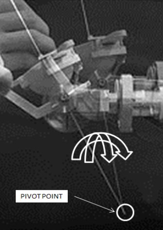
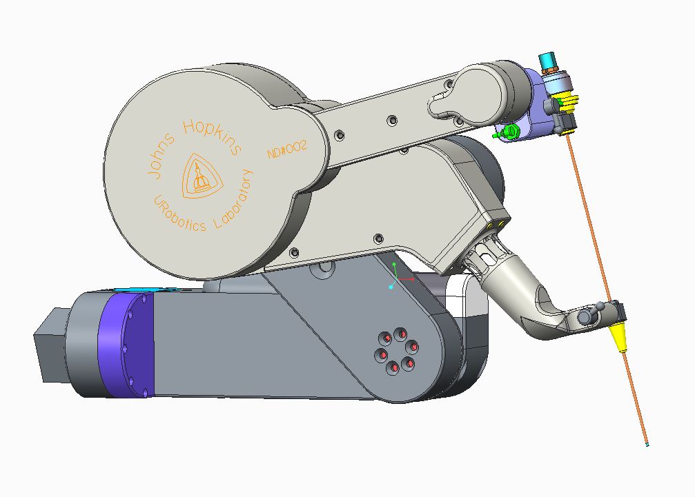 As it currently stands, there is a small but noticeable error ( 3mm ) in the location of the RCM. The RCM’s two axes of rotation are neither perpendicular nor intersecting, which causes it to move upon revolving either axis. This completely defeats the purpose of having an RCM, which offers the benefit of having a stationary pivot point around which it is possible to work. Since any error in the location of the RCM will cause even more errors to propagate along the linkage of the robot, a small displacement in the location of the RCM could lead to a very large displacement in the tip of the surgical device attached.
The goal for this project is to quantify and correct the RCM of the RND robot. We hope that by being able to track the tool tip very accurately with an optical tracker, we will learn how to build more precise and accurate RCM’s in the future.
- Students: Ryan Decker, Alex Vacharat, Changhan Jun
- Mentor(s): Dr. Stoianovici
Background, Specific Aims, and Significance
Many surgical robots today, such as the well-known da Vinci, have either mechanical or virtual RCM’s which allow them to operate in small spaces. By placing the RCM at the entry point in the patient, surgeons are able to obtain a very wide range of motion from a very small incision, which minimizes collateral tissue damage, blood loss, recovery time, scarring and infection.
 How much error is acceptable in the RCM is very much dependent upon the type of surgery being performed. For example, a 1mm difference in abdominal surgery is likely to be much less disastrous than a 1mm difference in ocular surgery. If RCM’s can be consistently and accurately maintained, surgeries requiring high precision will become much safer and easier to perform.
- RND ROBOT Animation
FPEki275WUc
Deliverables
- Minimum:
- Write a technical report on the accuracy and precision of the Polaris tracker
- Expected:
- Include in the technical report a comparison of multiple types of optical trackers
- Quantify the RCM error of the RND robot
- Mechanical dissection and analysis
- Maximum:
- RCM fixed based upon mechanical construction corrections
- Simplified systems identification (one or two parameters)
- Develop a new, more accurate kinematic model for the robot
Technical Approach
Polaris Tracker Accuracy Quantification
The manufacturer of the Polaris tracker states that the device has an error of 0.3mm, but they do not specify to what this 0.3mm refers to (overall displacement? Displacement in each cardinal direction?) Furthermore, they state nothing about the orientation of the markers.
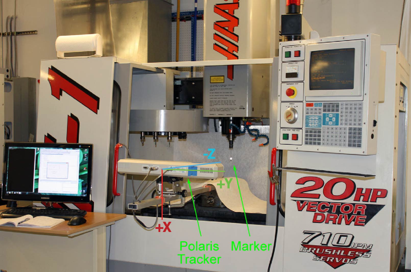 In order to determine a more accurate understanding of the capabilities of the tracker, we will use a highly accurate CNC machine to move the markers and give us a reference point. By using the CNC’s readings as the “expected” values (as the CNC has an accuracy on the order of a micron), we can better quantify the accuracy of the optical tracker.
In order to take the readings, the tracker is attached to the XY stage of the machine, and the marker is placed on the tool tip, or Z-stage. In doing so, we can precisely move the tracker and the marker to obtain readings in a 3D volume.
At each location within the CNC, 500 readings with the tracker are recorded. By doing so, the values can be denoisified and averaged to give a more accurate result that is unaffected by mechanical vibrations in the room. Furthermore, we hope to quantify the effects of taking readings at the trackers “sweet spot” and compare them to readings taken from other locations.
An extensive analysis on precision and accuracy, as well as repeatability of these tests will be performed. We also hope to test different types of trackers using our CNC method and compare the results.
RCM Error Quantification
Using the Polaris tracker, the RCM of the module will be observed in order to quantify the errors generated in the current state of construction. Markers will be placed at the tool tip, as well as a base reference, in order to more easily see the motion of the robot and its RCM. With the markers attached, the robot will be moved to several poses and orientations, taking measurements in a method similar to those of the CNC-comparison procedure.
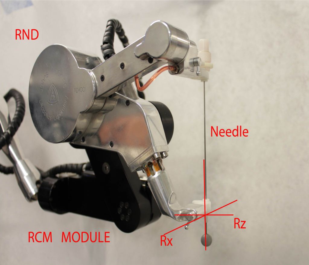 After performing these readings, we will have to two RCM axis locations relative to the tool tip in tracker space. We then want to compare these axis locations with the axis locations in our original CAD model.
Mechanical Dissection of the Robotic Needle Driver
The RCM of the RND robot will be partially disassembled and analyzed in order to study which factors contribute to the RCM error. The components of the robot, its link parameters, and axes of motion, will be compared with the ideal counterparts of the CAD model and corrected as much as possible, given the current design of the robot.
Dependencies
1. URobotics Laboratory Access
- Effect if not resolved: All equipment and software needed for this project is located in the laboratory. We cannot do significant work without access.
- Plan for resolution: We have key access to the lab.
2. CNC Machine Time - Needed to quantify the tracker accuracy.
- Effect if not resolved: Our entire project will be pushed back if we do not have time on the CNC machine, as the tracker is needed to quantify the RCM error.
- Plan for resolution: We have talked to Doru Petrisor and scheduled CNC time for the week of February 20th. We will acquire the data needed for the optical tracker paper during this time.
3. Time with RND - Needed to analyze, dissect, and fix RND.
- Effect if not resolved: All milestones and steps dealing with AcuBot will be pushed back while we do not have access to the robot. Other items, such as correcting unknown error in the Revolving Needle Driver robot, will be unaffected.
- Plan for resolution: We have talked to Dr. Stoianovici and secured time with RND throughout the semester.
4. Optical Tracker Time - Needed to calibrate tracker, measure errors, and implement the correction algorithm.
- Effect if not resolved: We will not be able to calibrate the tracker or use it to measure RCM error. This will push back our entire project
- Plan for resolution: We have talked to Chunwoo Kim, another lab member who uses the tracker, and scheduled time to use it throughout the semester.
Member Responsibilities
Note: All members will work on most portions of the project, however, the responsibilities listed below are the lead roles of which the members will assume
Alex:
- RCM / RND error analysis
- RND robot dissection,correction
- Kinematic Optimization
- Documentation and Web maintenance
Changhan
- CNC control and programming
- RCM / RND error analysis
- Mechanical RCM Correction
- Kinematic Modeling and Optimization
Ryan
- Optical tracker error analysis
- Serial port communications for optical tracker and CNC
- Mechanical RCM Correction
- Targeting test + Kinematic Optimization
Member Dependencies
- GCode for Marker Tracking - Changhan must write the GCode for each marker tracking test using the CNC machine. Needed to run the CNC optical tracker tests.
- Serial Communication - Ryan must develop a program to allow the CNC machine and the optical tracker to communicate. Needed to run the CNC optical tracker tests.
- RCM error analysis – The optical tracker error analysis needs to be done before the RCM error analysis can be performed.
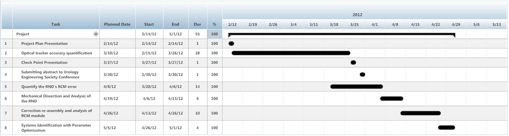
Milestones and Status
- Milestone name: Project plan presentation
- Planned Date: 14-Feb
- Completed Date: 14-Feb
- Status: Done
- Milestone name: Optical tracker accuracy quantification
- Planned Date: 10-Mar
- Completed Date: 26-Mar
- Status: Done
- Milestone name: Checkpoint Presentation
- Planned Date: 27-Mar
- Completed Date: 27-Mar
- Status: Done
- Milestone name: Submitting abstract to Urology Engineering Society Conference
- Planned Date: 30-Mar
- Completed Date: 30-Mar
- Status: Done
- Milestone name: Quantify the RND's RCM error
- Planned Date: 8-Apr
- Completed Date: 6-Apr
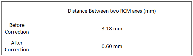
- Status: Done. Initial error at 3.6mm. Current analysis shows less than 1mm.
- Milestone name: Mechanical dissection and analysis of the RND
- Planned Date: 19-Apr
- Completed Date: 13-Apr
- Status: Done
- Milestone name: Correction reassembly and analysis of RCM module
- Planned Date: 26-Apr
- Status: Done Iterating analysis and correction to improve targeting.
- Milestone name: Systems Identification w/ Parameter Optimization
- Planned Date: 5-May
- Status: Done
Result
Polaris Optical tracking system Error Quantification
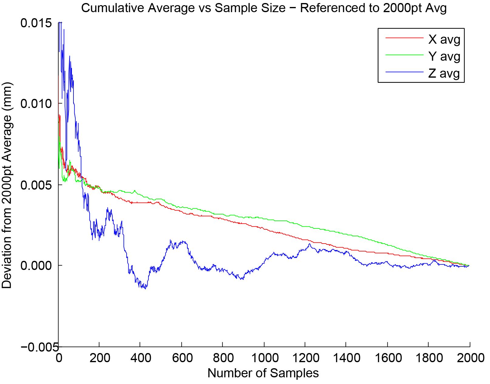
- Sample Size Study
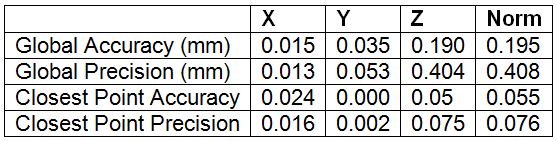
- Accuracy and Precision Result
RCM Error Quantification
- RCM Axes Correction Result
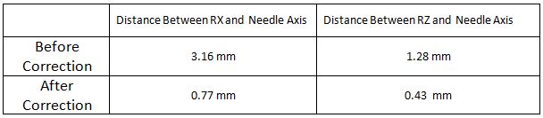
- Needle Axes Correction Result
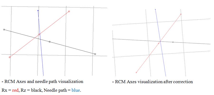
- Visualization of RCM Axes before and after Mechanical Correction

RCM Targeting Error Quantification
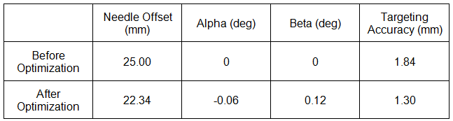
- Parameter Optimization Result
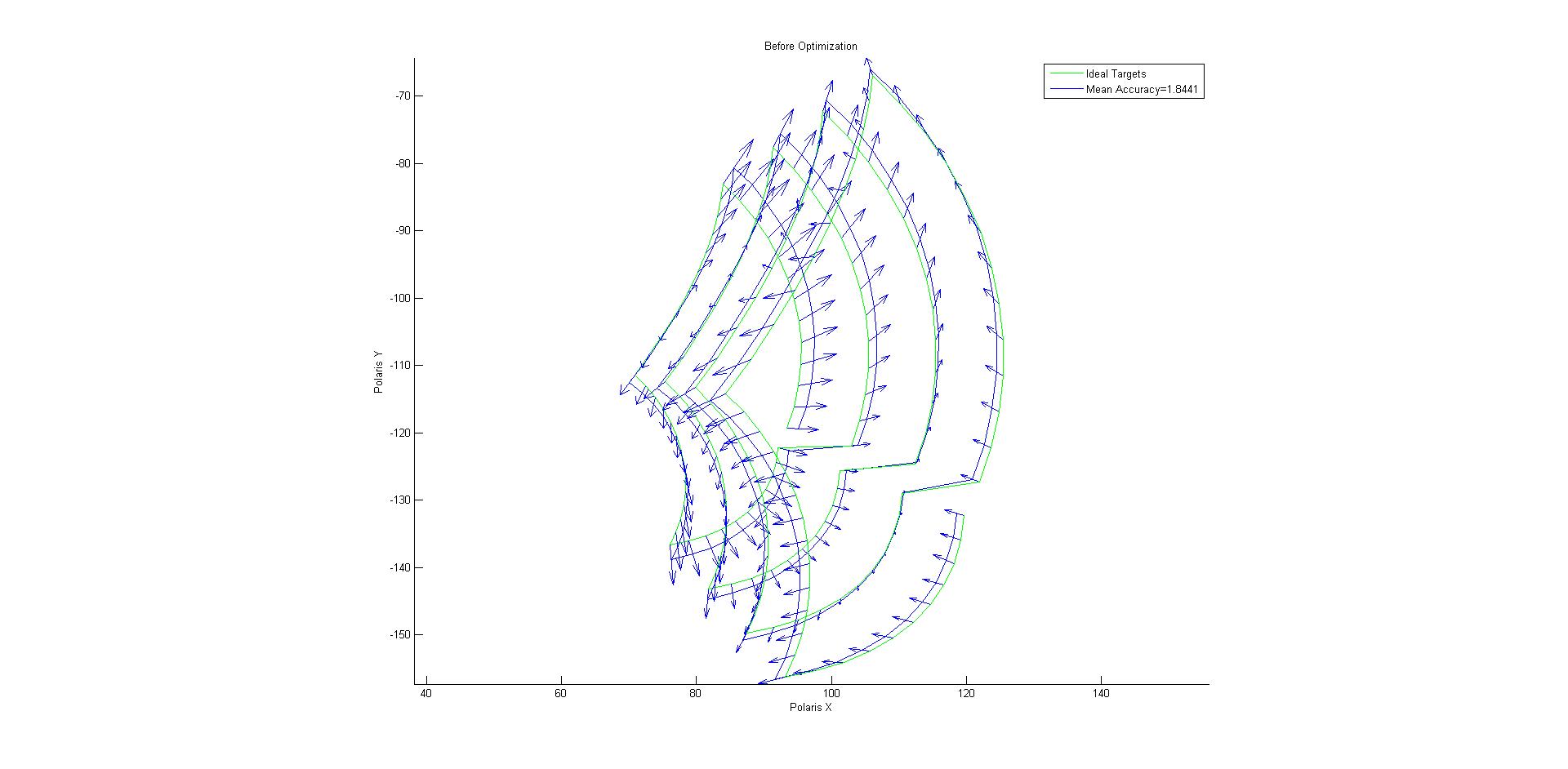
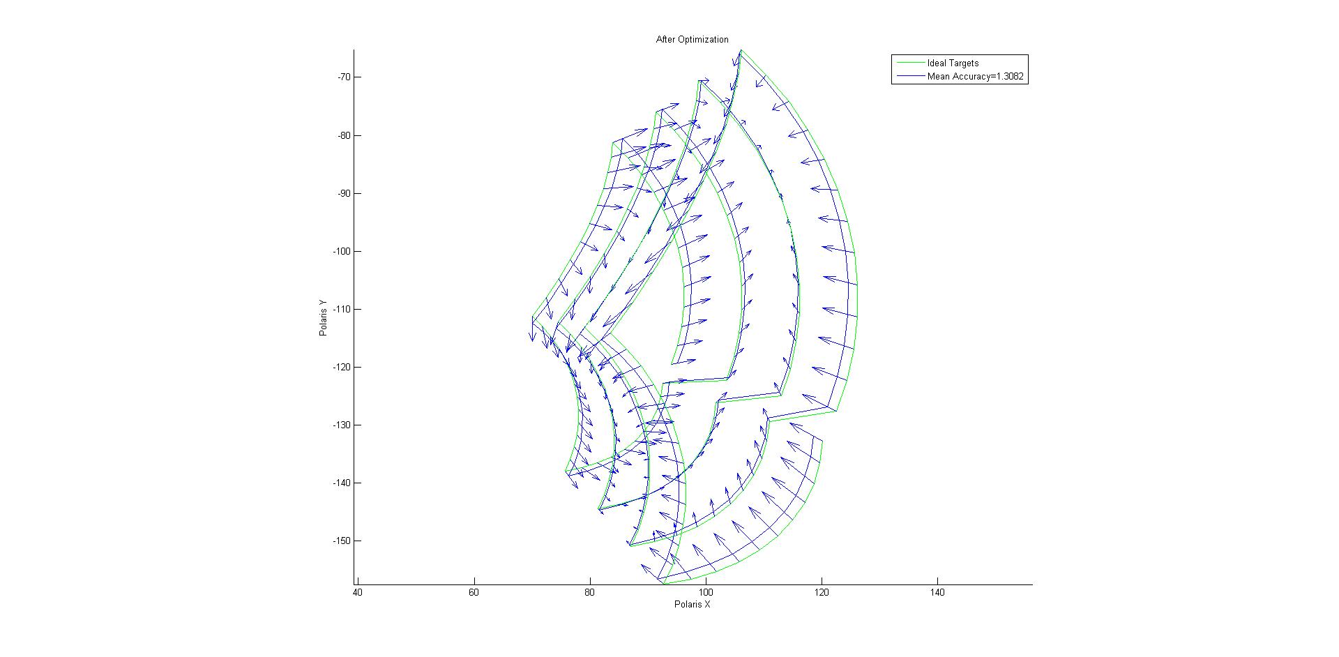
- Visualization of targeting errors before and after parameter optimization
Management Plan
- Team meetings Mondays, Wednesdays and Fridays 9am-5pm
- Mentor meetings Mondays, Wednesdays, Fridays, 1-2pm
TIME LINE
 (click to see in detail)
Reports and presentations
- Project Plan
- Project Background Reading
- See Bibliography below for links.
- Project Checkpoint
- Paper Seminar Presentations
- Project Final Presentation
- Project Final Report
Project Bibliography
Other Resources and Project Files
Here is a link to our code and data: https://www.dropbox.com/s/sfve3dj5v9gcfkt/DATA_Copy.zip