Contact Us
CiiS Lab
Johns Hopkins University
112 Hackerman Hall
3400 N. Charles Street
Baltimore, MD 21218
Directions
Lab Director
Russell Taylor
127 Hackerman Hall
rht@jhu.edu
Last updated: 5/3/16 4:15PM
Our goal is to bring the current Synthetic Tracked Aperture Ultrasound (STrAtUS) system from autopilot to co-robotic freehand. This will be done by implementing guidance virtual fixtures, force sensing, and compliance force control. Achieving these goals will essentially bridge the gap between an autonomous robot and direct control by the user. This will assist the operator in completing a safer and more accurate procedure.
Ultrasound imaging is widely used in the clinical setting to visualize a patient’s anatomy quickly, easily, and at a low cost. However, the main problem with ultrasound imaging is due to the aperture size of the transducer, which limits image quality in deep tissues. Synthetic aperture ultrasound imaging (STrAtUS) is a technique that synthesizes data from multiple sub-apertures using tracking data and has been shown to provide an improvement in image quality. The current synthetic aperture system uses a UR5 robot arm to autonomously scan the desired trajectory on the patient. This presents problems for clinical translation due to patient safety, ease of use by the sonographer, and force control requirements for anatomy-specific imaging.
Our goal is to bring the current system from autopilot to co-robotic freehand. This will be done by implementing guidance virtual fixtures, force sensing, and compliance force control. These goals are important because first and foremost, it will ensure patient safety. Secondly, it will allow for ease of use by the sonographer. Additionally, the force sensing and control component will allow for higher quality imaging of more complex regions, such as the abdomen, by guaranteeing a constant amount of force exerted.
Proposed system architecture
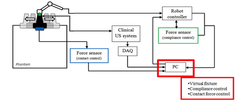
The currently proposed system is outlined in the figure below.
 Two force sensors are highlighted in blue and green. Data flows from these two sensors to the PC, and back to the robot controller.
The blue force sensor is proposed to be placed on the probe to detect the contact force with the phantom or patient, while the green force sensor is proposed to be placed at the wrist of the UR5 arm for compliance control. We currently possess the sensor highlighted in green, which is the Robotiq FT150, a 6-axis force-torque sensor. We have also been given permission to use the Futek LSB 200 from the AMIRo lab, run by Iulian Iordachita. This device is a uni-directional load cell that can measure forces up to 10 lbf (~44.5 N). For this project’s requirements, it may prove unnecessary to have both of these sensors since it might be preferable to pre-set a constant desired contact force. If this route is selected, the Robotiq FT150’s measuring capabilities will be sufficient and the Futek LSB 200 will not be required.
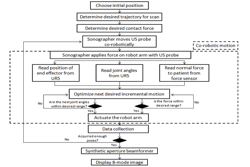
System Flowchart
The following flowchart represents how our virtual fixtures and force sensing will integrate with the current STrAtUS system. It demonstrates how the improved system with co-robotic control will be used together with input from the sonographer and creating the output of the B-mode image. Each of the components that are essential to this co-robotic control and how they serve to assist in image formation will be outlined in detail below.

Virtual Fixtures We propose to use a linearized, constrained optimization approach to implement the desired virtual fixtures. The idea of this approach is to lead the sonographer along the trajectory while providing haptic feedback to discourage deviation from the desired path. This will be done through the information gathered on the instantaneous kinematics of the manipulator, in addition to physical and geometric constraints. The objective function of the optimization problem generally takes the form argmin┬∆q‖W(J∆q ⃗-x ⃗_d)‖, where W is a diagonal weight matrix, J is the manipulator Jacobian that relates task space to joint space, q is the vector of joint variables, and xd is the desired Cartesian position. A general form of the constraints is given as H∆x ⃗≥h ⃗. The desired behavior of the system will be used in defining the linearized subject functions for H, the constraint coefficient matrix and h, the constraint vector. As mentioned, we want to guide the sonographer in moving the probe along a line. This is done by defining the equation of the line to be followed, calculating the error in each incremental motion, and bounding that error using the form outlined above. A similar method will be applied for constraining joint limits, following a curve instead of a line, and/or constraining the contact force on the patient. This simple formulation will allow us to add more constraints as we see fit over the course of our development.
Compliance Control
We additionally propose to implement compliance robot force control for the use of ultrasound probe guidance in synthetic aperture applications.
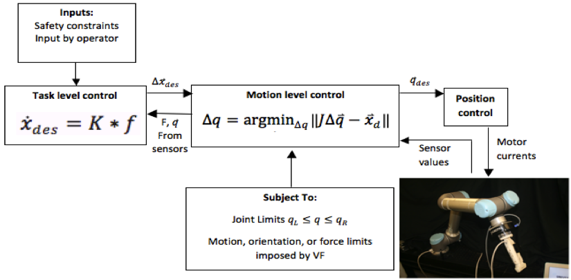
In short, force and torque readings acquired through the Robotiq FT 150 sensor will be translated into incremental joint motions of the UR5. The relationship between the forces exerted by the clinician against the robot end effector (EE) when manipulating the ultrasound probe takes the form x ̇_des=K*f where K, typically determined experimentally, is a coefficient matrix that scales the input force to an appropriate EE velocity in Cartesian coordinates. From this EE velocity vector, the corresponding joint velocities are calculated using x ̇=Jq ̇→q ̇=J^(-1) x ̇ where J is the robot Jacobian matrix. As seen on the right-hand side of this equation, the inverse of the Jacobian must be calculated to determine the joint velocities. However, to avoid cases where the Jacbobian cannot be inverted, an optimization method can be employed, resulting in the formulation q ̇=argmin┬q ̇ ‖Jq ̇-x ̇ ‖ where the joint velocity vector that minimizes the objective function is calculated.
For safety purposes, it is important to consider the situation in which the connection between the robot controller and the computer sending the velocity commands is broken. In particular, if the connection is broken while the robot is in motion due to a previously received velocity command, the UR5 will not receive any new commands and will continue to move at the same velocity. In order to avoid this, a common technique is to instead send the robot incremental joint angle commands. This is done by changing the optimization problem to ∆q=argmin┬∆q‖J∆q ⃑-x ⃑_d ‖ where x is the desired end effector position and ∆q is the resulting incremental joint commands. This results in the objective function shown in the “Virtual Fixtures” section above.
The figure below shows the relationship between the robot, force sensor, and probe. Overall, this method will be used to allow for smooth and intuitive clinician-robot interactions and will allow the user to have control of the velocity at which the probe moves down the desired trajectory. Combined with virtual fixtures, this collaborative control will ensure smooth, accurate, and safe ultrasound image acquisition at a velocity that is most comfortable for the sonographer.

Image formation The details above highlight the important components of using co-robotic control for STrAtUS imaging. The main goal of improving ultrasound image quality is obtained through tracking the transducer, which in this case is achieved through the inherent and highly accurate mechanical tracking properties of a robotic arm. This tracking of the ultrasound probe allows for data from multiple poses to be reconstructed to form a single, higher resolution image. As can be seen in the flowchart in Figure 2, the sonographer determines the initial pose, which will serve as the base image frame during reconstruction, and then collects data aided by the virtual fixtures and compliance control in order to construct the desired image.
Access to UR5 robot and force sensors - MUSiiC Lab Google Calendar (Done) Access to Sonix Touch ultrasound system – Done Access to STrAtUS real-time visualization system - Done Access to mentors - Weekly meeting with Kai Access to water tank & phantoms - Available in lab space Deeper understanding of virtual fixtures and implementation- Done Familiarity with CISST libraries- Ongoing
If the status of any of these dependencies changes to our detriment, we will discuss with our mentors how best to proceed. However, it would not be impossible to proceed. In terms of the UR5 robot, the MUSiiC lab shares a second robot with the BIGSS lab run by Dr. Mehran Armand. We would have access to this robot should anything happen to the other. The STrAtUS visualization system is a software application that has been backed up many times. Lastly, the water tank and phantoms are easily replaceable should anything happen to the existing ones.
Abbott, Jake J., Panadda Marayong, and Allison M. Okamura. “Haptic virtual fixtures for robot-assisted manipulation.” Robotics research. Springer Berlin Heidelberg, 2007. 49-64.
Funda, R. Taylor, B. Eldridge, S. Gomory, and K. Gruben, “Constrained Cartesian motion control for teleoperated surgical robots,” IEEE Transactions on Robotics and Automation, vol. 12, pp. 453-466, 1996.
A. Kapoor and R. Taylor, “A Constrained Optimization Approach to Virtual Fixtures for Multi-Handed Tasks,” in IEEE International Conference on Robotics and Automation (ICRA), Pasadena, 2008, pp. 3401-3406.
M. Li, M. Ishii, and R. H. Taylor, “Spatial Motion Constraints in Medical Robot Using Virtual Fixtures Generated by Anatomy,” IEEE Transactions on Robotics, vol. 2, pp. 1270-1275, 2006.
M. Li, A. Kapoor, and R. H. Taylor, “A constrained optimization approach to virtual fixtures,” in IROS, 2005, pp. 1408–1413.
S. Payandeh and Z. Stanisic, “On Application of Virtual Fixtures as an Aid for Telemanipulation and Training,” Symposium on Haptic Interfaces for Virtual Environment and Teleoperator Systems, 2002. R. H. Taylor, J. Funda, B. Eldgridge, S. Gomory, K. Gruben, D. LaRose, M. Talamini, L. Kavoussi, and J. anderson, “Telerobotic assistant for laparoscopic surgery.”, IEEE Eng Med Biol, vol. 14- 3, pp. 279-288, 1995
Ankur Kapoor, Motion Constrained Control of Robots for Dexterous Surgical Tasks, Ph.D. Thesis in Computer Science, The Johns Hopkins University, Baltimore, September 2007
A. Kapoor, M. Li, and R. H. Taylor “Constrained Control for Surgical Assistant Robots,” in IEEE Int. Conference on Robotics and Automation, Orlando, 2006, pp. 231-236. R. Kumar, An Augmented Steady Hand System for Precise Micromanipulation, Ph.D thesis in Computer Science, The Johns Hopkins University, Baltimore, 2001. - cannot find
M. Li, Intelligent Robotic Surgical Assistance for Sinus Surgery, PhD Thesis in Computer Science Baltimore, Maryland: The Johns Hopkins University, 2005.
J. Roy and L. L. Whitcomb, “Adaptive Force Control of Position Controlled Robots: Theory and Experiment”, IEEE Transactions on Robotics and Automation, vol. 18- 2, pp. 121-137, April 2002
R. Taylor, P. Jensen, L. Whitcomb, A. Barnes, R. Kumar, D. Stoianovici, P. Gupta, Z. Wang, E. deJuan, and L. Kavoussi, “A Steady-Hand Robotic System for Microsurgical Augmentation”, International Journal of Robotics Research, vol. 18- 12, pp. 1201-1210, 1999
sawConstraintController and Constrainted Optimization JHU-saw library page on Virtual Fixtures
Here give list of other project files (e.g., source code) associated with the project. If these are online give a link to an appropriate external repository or to uploaded media files under this name space.