Contact Us
CiiS Lab
Johns Hopkins University
112 Hackerman Hall
3400 N. Charles Street
Baltimore, MD 21218
Directions
Lab Director
Russell Taylor
127 Hackerman Hall
rht@jhu.edu
Last updated: 2020 Feb 24 and 11.11 pm
Develop a visualization system that utilizes augmented reality to help surgeons have better view in orbital floor reconstruction.
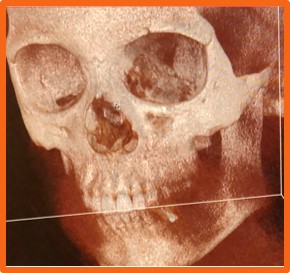 Figure 1. The fractured eye socket
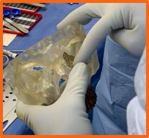 Figure 2. The placing of the orbital floor implant
Due to pressure on the eye from blunt trauma, the medial wall and orbital floor can fracture. Fracture repair requires manipulation of delicate and complex structures in a tight, compact space. Surgeons struggle with visibility in the confined region.
A concave plate is placed along the wall of the eye socket to prevent tissue from entering fracture cavity. The major complexities are hard to place the implants, low visibility, misplacement can result in injury to sensitive tissue, and long operating time.
Orbital floor reconstruction surgery is a long and arduous process, requiring significant attention from the surgeon and manipulation of delicate and complex structures in a tight, compact space. Due to the nature of the orbital floor bone and manner in which it may fracture, shattered bone fragments may be present scattered in the maxillary sinus and in other regions within the operative field.
The orbital aperture is a tightly confined space due to the fact that its primary purpose is to provide structure of the ocular system. As a result, a fracture in the orbital aperture is difficult access since it is within the compact space. Additionally, any incision made in order to access the tissue underneath is relatively small, giving surgeons limited visibility into the orbital aperture. As a result, it is difficult for surgeons to develop context and orientation of the anatomy once they have dissected along the orbital wall. This sense of orientation is necessary, as placement of the orbital implant plate requires precise shaping of the implant and identification of the posterior lip of fracture. The implant must rest on this bony structure into order to remain securely in place. Since the posterior lip is towards the backside of the orbital aperture, it can take surgeons multiple attempts before they feel confident that the implant is resting on the posterior wall as they struggle to see its location through the relatively small incision and following dissection.
This relative operative blindness is an indication of a clear need for improved surgical navigation and visualization techniques specific for orbital floor reconstruction. An augmented reality assisted orbital floor reconstruction system is proposed to resolve the problem of low visibility of the distal orbital wall during the procedure, so that misplacement may be avoided. The introduction of a head mounted display to provide navigation to surgeons in the orbital floor implant process would reduce operation time and increase surgeon confidence in secure implant placement.
The following deliverables are all expected before the end of the semester (final presentation).
Two anatomic features are selected to calculate the target registration error: temporal bone tip and the intersection of the zygomatic bone and superaorbital margin. The CT model (converted to left handedness) coordinates for these two anatomic features can be shown in the following figures. The TRE for fiducial-based registration on these two anatomic features are calculated to be 1.6366 mm and 1.0700 mm, respectively.
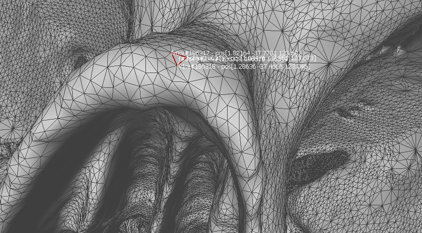 Figure 3. Temporal bone tip target coordinate
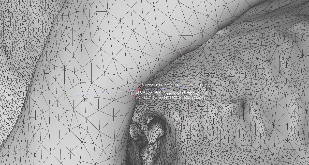 Figure 4. The intersection of zygomatic bone and superaor-bital margin coordinate
 Figure 5. The target registration errors calculated for both anatomic features
The average registration residual is calculated to be 0.63 mm and 2.33 mm for fiducial-based registration and fiducial-initialized ICP registration, respectively.
Although the average residual of ICP registration was low, the TRE was tested to be high. We conclude that it did not converge for the points we collected specifically. By comparing the derived transformations of fiducial-based registration and ICP, we found that rotation matrix did not differ too much but the position offset changed by a lot (around 10 mm in both x axis and y axis, 1 mm in z aixs). We conclude that the ICP made the fiducial-based registration worse. However, the fiducial-based registration works well in our case.
The visualization is done by Unity webcam appli-cation. It can also be compiled to be a HoloLensapplication so the user can use the system in head-mounted display. The skull model overlay is suc-cessfully made while the implant motion is not sta-ble, although the static pose and position was testedto be correct. This can be solved by a better mov-ing method in Unity frame update. The skull modeloverlay can be seen in the following figure.
The implant used to validate the calibration processof the system was an orbital floor implant sample from the manufacturer, DePuy Synthes. To com-plete the calibration process, points were capturedalong the sides and on the edges of the grids withinthe implant. These points were captured using thetracked pointer tool of the Polaris system. Prior tothis step, the implant was securely clamped by thehemostat, as shown below.
After points were captured, the data was thenparsed by the calibration code and digitized. Usinga number of python packages including pyvista, pymeshfix, and vtk, a surface mesh of triangleswas created from the digitized points. It was ob-served that the greater number of points collectedresulted in a more accurate surface mesh. The accu-racy of the implant model is a key portion of makingthe system functional. Though point collection cantake 1 to 2 minutes, it is paramount that a largenumber of points be collected to ensure that themodel is as accurate as possible.
Once a surface mesh is made, a thickness factoris added to the mesh. First, the surface mesh isextruded using the vtk package. It is important tonote that this is thickness must be measured fromthe implant directly in order to maintain the bestaccuracy. Once this thickness is added, pymesh-fixis used to rid the new mesh of any potential non-manifold faces. This step is crucial in ensuring that the mesh not have any faces that cannotexist in the real world. This includes faces within faces and other triangles in the mesh that are intersecting each other. After the mesh has been rid of these deformities, it is then tetrahedralized to giveit a 3D shape. This step is crucial to ensure that the implant is visible in the visualization portion of the system. A plain surface mesh will not be visible in the visualization due to the fact that has no thickness.
The project was originally attempted using existing libraries (mostly from cisst software library), however, the implementation involves the use of other customized software. The major components can be seen in the following chart, which also doubles as our coordinate system diagram. Below that is a system diagram.
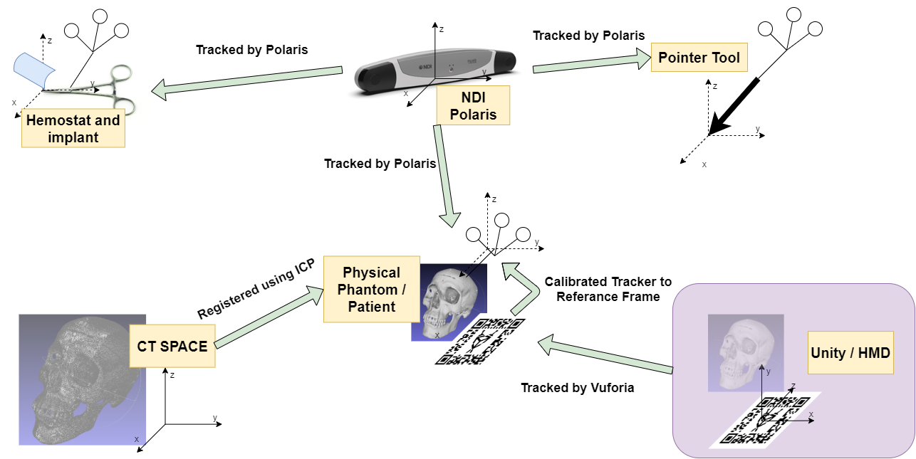 Figure 8. The coordinate system diagram
The transformation map can be viewed in the coordinate system diagram figure (Figure 8). The three unknown transformation relations are the transformation from the Unity/HMD space to the physical skull space, the transformation from the tracked AR marker to the physical skull space, and the transformation from CT spaceto the physical skull space. The Python server is implemented to solve these transformations. Iterative closest point algorithm can be used to getthe transformation from CT to skull. And the AR marker can be tracked by Vuforia virtual reality engine that is integrated in Unity. To get the transformation from AR marker to the skull, we simplyused a point cloud registration by getting the fourcorners of the AR marker in skull space to the desired corresponding points in virtual space.
The user procedure includes five steps that was showed in the Figure 12. The calibration methodis pivot calibration. Then, the model samplingmethod allows the user to specify frequency and the number of the points the user needs to take.The sampling method also allows the user to specify which tracked tool to be the base coordinatesystem. After that, the implant model is createdby Delaunay triangulation. In order to give the implant surface a thickness, we can use the Uniform Mesh Resampling in Meshlab, or using thepymesh-fix library available in Python. The registration and transformation calculation is then carried outbased upon the transformation map that was discussed in Section 5.1 Transformation Map. Among these steps, handedness handling should be made.There are two different methods to handle handedness which will be discussed in Left Handedness. Now the transformation (the pose of the skull and implant model) be can send to the Unity client for visualization.
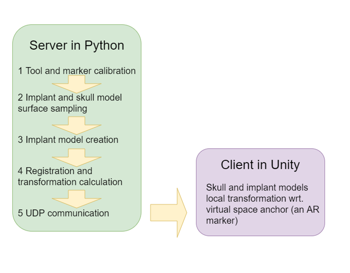 Figure 9. System diagram
The data collection will be made through NDI Polaris camera and will be transmitted by via adapted UDP process. A Windows PC will be used to run the algorithms. The system may require more computers to run the Unity algorithm and registration/calibration algorithms separately.
Polaris camera is used to get the tracker coordinates by scikit-surgerynditracker package for python, with adaptations specific for our application. For the registration process, the received coordinate data is the coordinates data of the passive trackers on a pointer, which will be used to collect the coordinate of the pointer tip. The pointer tip collects the point cloud which will be used for registration. Once a sufficient point cloud is collected, it will be sent along with the CT model data to Iterative Closest Point (ICP) algorithm. For the calibration process, the received Polaris data is again the coordinates of the passive trackers attached to the pointer. The pointer will be used to collect the coordinates of the distal edge (expected deliverable) or a complete point cloud (maximum deliverable) of the implant.
Unity and/or Hololens will be used to model and visualize the implant.
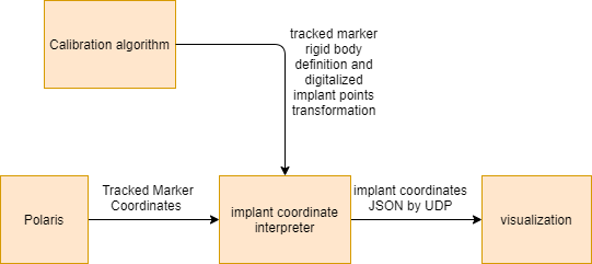 Figure 10. Visualization block diagram
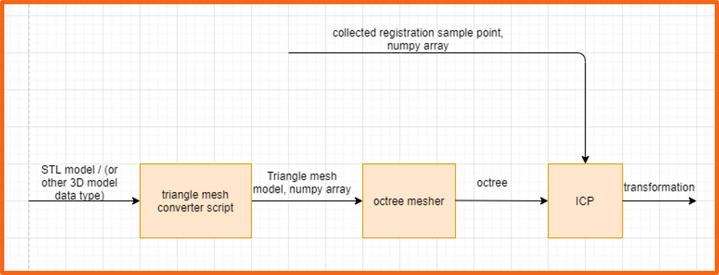 Figure 11. The registration block diagram
Unity uses a convention of left handedness, whileall the other coordinate systems (Polaris, CD models etc.) are in right handedness. This problemis solved by two different methods, and there aretwo different branches in the Github repository.The “master” branch handles the handedness by “Calculate, convert, send”, while the “lefthanded” branch handles the handedness by “Convert, calculate, send”. More specifically, the “Calculate, con-vert, send” method means to calculate the transformations under assumption that all the coordinate systems are in right handedness, then only the desired results are converted to lefthandedness andsent to Unity client. On the other hand, the “Convert, calculate, send” methods corresponds to converting all the coordinate system to lefthandedness initially and then conduct procedures needed. In “Convert, calculate, send” method, the skull modelused in ICP is flipped along x-axis to match the Unity. In the Polaris collection, all the x, y, and z are flipped to have a left handed coordinate while not changing the rotation matrix.
We used the older version of Polaris optical trackerby Northern Digital Inc. In this project, the raw Polaris data collection hardware interface used is the scikit surgeryn-ditrackerlibrary developed by Wellcome EPSRC Centre for Interventional and Surgical Sciences at University College London. It is a light-weightedpackage that is easy to customize. There are two known issues when working with this package. One is that on Windows development environment, itonly properly installs under Python 3.6. However, Python 3.7 works for both Linux and MacOS development environment. The other problem is that an UnicodeDecodeErroris reported when using 3 tracked bodies and the system uses “BX Transforms”, which can be fixed by changing source code in nditracker.py to “TX Transforms”. The same problem also happens when using 1 tracked body and the system uses “TX Transforms”. To customize the interface, a polarisUtilityScript.py is created. This script is located in the serverPython/util folder of the project repository. To improve code reusability, the point collection method is made to be able to collect point directly with respect to another tracked tool. This largely decreases the transformation calculation procedure. Details can be seen in the polarisUtilityScript.py script.
Vuforia is a augmented reality engine that is integrated in Unity. One important feature in Vuforia is the image tracking feature. Vuforia tracks an imageand estimate the pose of the image. We utilize this feature to complete our transformation chain. However, sometimes the Vuforia engine takes a flipped pose of a horizontal marker. The effect can be seen in the following figure. We found Vuforia is more capable to successfully calculate a vertical AR marker pose.
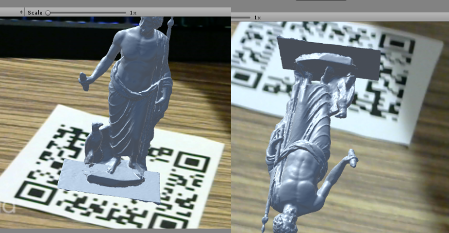 Figure 12. The wrong Vuforia tracking
Although the transformation can be accurately calculated, the accuracy is still limited by the Vuforia image tracking. To improve the accuracy of themodel overlay, a calibration procedure may need tobe done. A calibration work done by Azimi et al (E.Azimi, L.Qian, N.Navab, and P. Kazanzides. Alignment of the virtual scene to the tracking space of a mixed reality head-mounted display. Retrieved from: https://arxiv.org/pdf/1703.05834.pdf, 2019.) can be a solution. This calibration procedurerequires a tracked head mounted display.
After parsing the point calibration data collectedfrom the tracker pointer on the implant clamped to the hemostat, a surface mesh could be created of the digitized points using the pymesh package however, this model would not appear in the visualization. After inspection, it was determined thatthickness would need to be added to the surfacemesh. This proved to be difficult as a simple extrusion of the surface mesh would simply yield another surface mesh. In order to tetrahedral the surface, several packages were attempted to be used to accomplish the task, yet all yielded the same error, Cannot tetrahedralize non-manifold mesh. After researching the definition of a manifold mesh, it was difficult to determine a remedy to the issue without having to load the surface mesh into a computer-aided design software to remove all non-manifold vertices within the model. However, after somemore research, it was determined that it could bedone within the code using the pymeshfix package. Unfortunately, after this step, the tetrahedralizedmesh turned out to not be Representative of theactual geometry. Up till this point thickness was only added in one cardinal direction. After some experimentation, it was discovered that in order tohave the most accurate 3D model, thickness mustbe added in all three cardinal directions.
* Please note the technical details will be added and maybe modified along the development process.
Dependencies, Solution, Alternatives, and Status
Main project repo: https://github.com/bingogome/CISII_Orbital
The figure below illustrates the portions of theproject that were done by each member. The figure is broken down to reflect the amount done byeach party for each of the three deliverable categories. Both parties worked in conjunction on thepresentations and reports. Documentation of thesystem was also done in conjunction, depending onthe party involved on that aspect of the project.Due to the coronavirus outbreak, the project hadto be split up according to the resources availableto each member. Fortunately, we were still able to achieve the declared deliverables.
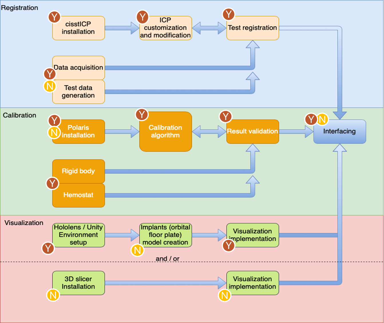 Figure 13. Breakdown of Portions of project done by each party, the yellow encircled letter N representing Nikhil Dave and brown encircled letter Y representing Yihao Liu
Both members of the team learned a considerable amount from the implementation of this project. This was not just limited to the technical skills required to develop the project. In particular, the following lessons were learned below.
While achieving the assigned deliverables was an accomplishment for the semester, the primary objective for the project is to develop a functional, highly accurate augmented reality navigation system; ideally visualized through Microsoft’s HoloLens. Having created a functional Unity application, it is not unrealistic to say that a functional HoloLens application is possible in the near future. Developing such an application of a head mounted display(HMD) will provide the surgeon’s with the mostmost practical visualization method. While previous studies have shown that these systems struggle with providing accurate enough visualization forsurgical procedures, from consultations with surgeons, an HMD based visualization would providethe surgeon with the most benefit in comparison toalternatives. A clear view of operative field in addition to the information provided by the system,would make for an excellent and desirable tool inthe operating room with little discomfort for surgeons and lead to better patient outcomes.
Having made significant headway into this part ofthe project, it would also not be unrealistic to continue to develop this method of visualization. Asstated in previous sections, the development of this portion of the project was not to far from completion and could provide a great deal of validation tothe future Hololens application by providing a direct comparison to identify the strengths and weaknesses of both systems. By developing the 3D-Slicer visualization further, a baseline standard of visualization can be established. Thus, a more empirical validation of the future HoloLens application’sability to visualize the system information can beachieved.
The goal of any computer integrated system is toeventually see use. As an engineer, it is very common to get lost in the technicality of a project. While such an intense focus can be beneficial in developing a functional system, other aspects of theoverall system can be neglected, particularly usability. In order to ensure that the system is simple andintuitive to use for surgeons, it is imperative that
user studies be conducted to empirically evaluate aspects of the system that are not user friendly oractually turn out to prevent the accomplishment of system goals. Testing the system in this manner, isa clear and effective way to ensure that the work-flow of the system is sensible and therefore lead toa more functional product. Such user studies neednot be done on a patient, but can be tested on ananatomically similar phantom.
Once the system has been validated through userand cadaver studies, in order to see clinical use, clinical trials have to be done, along with approval fromthe U.S. Food and Drug Administration. Clinicaltrials provide a snapshot into how the system actually impacts the outcome of patients. This is thefinal critical validation step of developing a func-tional and successful product. As a primary goal of this project is to develop a computer-integrated surgical system that improves the outcome of patients and reduce operating time, clinical trials provide asnapshot to how the system can execute its goals and will be necessary to bring this system into usein the operating room.
We would like to acknowledge our mentors Dr. Pe-ter Kazanzides and Ehsan Azimi for continually meeting with us to answer our questions and givingus development suggestions. We would also like to acknowledge Anton Deguet for helping use the cisstlibraries and also providing suggestions for the development of the project. We would like to thank our clinical mentors Dr. Cecil Qiu and Dr. Sashank Reddy, for allowing us to shadow a procedure aswell as providing us with information regarding thenature of the procedure and the usability of our application. Our clinical mentors were also instrumental in providing us with the clinical material necessary to develop the project. Finally, we would like to thank Wenhao Gu for help in developing the Unity visualization application.