Integration of CBCT and a Skull Base Drilling Robot
Summary
The performance of a Skull Base Drilling Robot is limited in cadaver studies mainly due to registration error in current system. In this project, a C-arm cone-beam CT will be used to provide guidance and “no-fly zones” to the robot that properly accounted for anatomical deformations imparted during the surgery. Hopefully, this integration will reduce registration error and improve the performance of the robot in cadaver studies.
Students: Hao Dang, Zihan Chen
Mentor(s): Jeff Siewerdsen, Peter Kazanzides
Course Mentor: Russ Taylor
Background, Specific Aims, and Significance
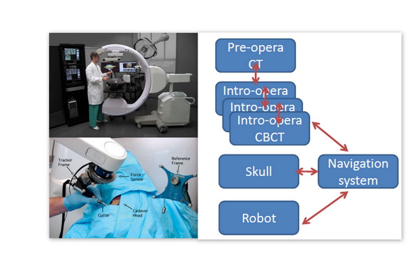
Neurosurgeries such as skull base surgeries are often challenging due to the complex anatomy and the critical nature of adjacent neural and vascular structures. The use of image-guided robots in neurosurgeries can provide precise intra-operative guidance and mechanical assistance. Current skull base robot system developed in Prof. Kazanzides’ lab integrated a Stealthstation navigation system, a NeuroMate robotic arm with a six degree-of-freedom force sensor, and 3D Slicer visualization software to allow the use of the robotic arm in a navigated, cooperatively-controlled fashion by the surgeon. Pre-defined virtual fixture has also been developed to constrain the motion of the robot-held cutting tool within safe zone. The system yielded high accuracy in phantom study–0.6 mm average placement error and 0.6 mm average dimensional error. But in cadaver study some bone outside virtual fixture was cut and the typical overcut was 1–2 mm, with maximum about 3 mm. This keeps the robot from being further tested in real clinical trial.
Considering that intra-operatively updating anatomical deformation and registration may be a possible way to increase cutting accuracy, an advanced intra-operative imaging device–C-arm cone-beam CT will be integrated into the robot system. This prototype CBCT imaging system based on a mobile isocentric C-arm has been developed in Prof. Jeff Siewerdsen’s lab in collaboration with Siemens Healthcare (Siemens SP, Erlangen Germany). It has demonstrated sub-mm 3D spatial resolution and soft tissue visibility which are suitable for neurosurgery navigation. The typical acquisition and reconstruction time are ~60s and ~20s respectively which will not interrupt the surgical workflow.
Our specific aims are:
1. Fusion of intro-opera CBCT and pre-opera CT images by fiducial-based rigid registration
2. Construct complete transformation flow including robot, skull, CBCT images with navigation system. Perform phantom experiments using CBCT-Guided skull base drilling Robot system (‘CGR’ system) with navigation.
3. Construct another transformation flow without navigation system. Perform parallel phantom experiments using the two CGR system above (with and without navigation) and previous non-CBCT system. Make comparison and analysis.
Deliverables
Minimum:
1. Fusion of intro-opera CBCT and pre-opera CT images by fiducial-based rigid registration.
2. Complete transformation flow including robot, skull, CBCT images along with navigation system.
3. Target-pointing experiment on phantom using CBCT-Guided skull base drilling Robot system (‘CGR’ system) along with navigation.
Expected:
1. Foam-drilling experiment on phantom using CGR system with navigation.
2. Another transformation flow including robot, skull, CBCT images without navigation system.
3. Parallel phantom experiments using the two CGR system above (with and without navigation) and previous non-CBCT system. A comparison report.
Maximum:
Technical Approach
1. Robot System with CBCT and Navigation System
Pre-operation
Obtain CT Image of Skull Base
Create virtual fixture on CT image in TREK
Obtain CBCT Image of Skull Base
CBCT to CT registration
CBCT to Skull (relative to tracker) registration
Robot to Dynamic Reference Base (relative to tracker)registration(Dynamic Reference Base is mounted on the head clamp)
Get tip position with reference to Robot World frame
Get tip position with reference to DRB frame
Attach rigid body to robot cutting tool
Do pivot calibration to get cutter tip position with reference to robot rigid body frame
Calculate tip position with reference to DRB frame using navigation system
Paired-point registration
Register virtual fixture from CT image frame to Robot World frame using the transformation flow above, prevent tool from entering “no-fly-zone”
Intra-operation
A neurosurgeon holds the robotic arm and drills in cooperatively controlled fashion guided by CBCT image and navigation system and protected by virtual fixture
Obtain CBCT images after achieving each milestone in surgery
Register new CBCT image to earlier ones, update deformation information and virtual fixture
Post-operation
2. Robot System with CBCT but without Navigation System
Milestones and Progress
Milestone name: Registering CT image coordinate to NDI Tracker coordinate
Milestone name: Registering CT image coordinate to CBCT image coordinate
Milestone name: Registering robot world coordinate to NDI Tracker coordinate
Milestone name: Robot program has access to NDI Tracker data via robot-tracker interface
Milestone name: 3D Slicer displays the position of robot cutter-tip in real time via OpenIGTLink
Milestone name: Experiment 1–Target fiducials on phantom
Milestone name: Experiment 2–Drill a space with Virtual Fixture on phantom
Major changes or issues
Results
Reports and presentations
NOTE: In uploading media, upload them to your own name space or to private sub-namespace, depending on whether the general public should be able to see them.
Project Bibliography
Robotic system
1. Accuracy Improvement of a Neurosurgical Robot System.HaideggerT., Tian Xia, Kazanzides, P.Biomedical Robotics and Biomechatronics, 2008. 2nd IEEE RAS & EMBS International Conference on, pages 836 – 841, 27 January 2009
2. An integrated system for planning, navigation and robotic assistance for skull base surgery.Tian Xia, Clint Baird, George Jallo, Kathryn Hayes, Nobuyuki Nakajima, Nobuhiko Hata, Peter Kazanzides*. The International Journal of Medical Robotics and Computer Assisted Surgery, Volume 4, Issue 4, pages 321–330, December 2008
C-Arm Cone Bean CT
1. Siewerdsen JH, Daly MJ, Chan H, Nithiananthan S, Hamming N, Brock KK, and Irish JC, “High-performance intraoperative cone-beam CT on a mobile C-arm: An integrated system for guidance of head and neck surgery,” Proc. SPIE Visualization and Image-Guided Procedures Vol. 7261: 72610J-1 – 72610J-8 (2009).
2. Nithiananthan S, Brock KK, Daly MJ, Chan H, Irish JC, and Siewerdsen JH, “Demons deformable registration for cone-beam CT guidance: Registration or pre- and intra-operative images,” Proc. SPIE Visualization and Image-Guided Procedures, Vol. 7265: 72650L-1:7 (2010).
3. Hamming NM, Daly MJ, Irish JC, and Siewerdsen JH, “Automatic image-to-world registration based on x-ray projections in cone-beam CT-guided interventions,” Med. Phys. 36(5): 1800-1812 (2009).
4. Bachar G, Barker E, Chan H, Daly MJ, Nithiananthan S, Vescan A, Irish JC, and Siewerdsen JH, “Visualization of anterior skull base defects with intraoperative cone-beam CT,” Head and Neck 32(4): 504-512 (2010).
5. Daly MJ, Siewerdsen JH, Cho YB, Jaffray DA, and Irish JC, “Geometric calibration of a cone-beam CT-capable mobile C-arm,” Med. Phys. 35(5): 2124-2136 (2008).
Other Resources and Project Files
Here give list of other project files (e.g., source code) associated with the project. If these are online give a link to an appropriate external repository or to uploaded media files under this name space.


