Contact Us
CiiS Lab
Johns Hopkins University
112 Hackerman Hall
3400 N. Charles Street
Baltimore, MD 21218
Directions
Lab Director
Russell Taylor
127 Hackerman Hall
rht@jhu.edu

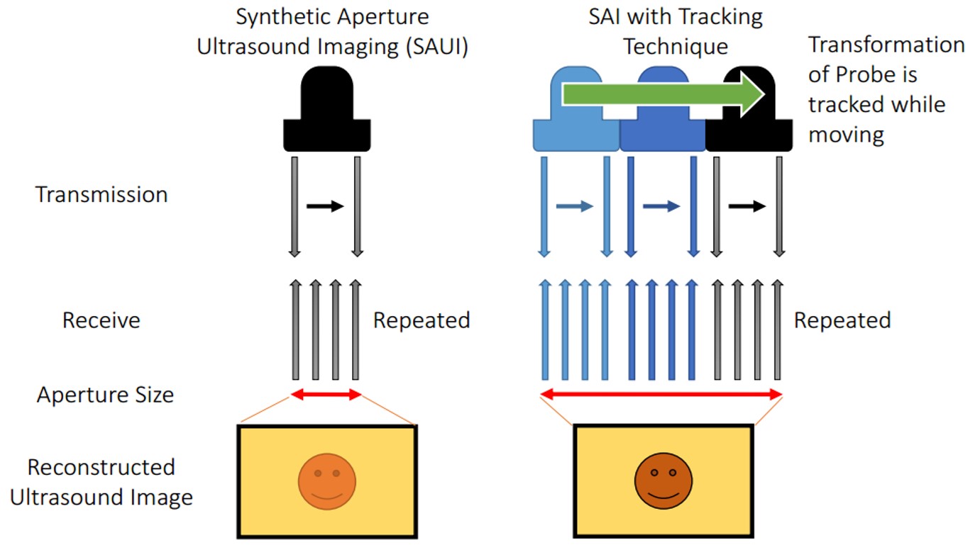
Synthetic aperture is a technique to synthesize transmit and receive elements to ensure wider aperture for reconstruction. However, the maximum aperture size can be used is restricted by the physical size of the ultrasound transducer, and this results in high F number in deep sight. We propose a method to expand the aperture size by sweeping the probe using a robotic arm. Received signals can be synthesized, and the widened aperture can be used in reconstruction. The work starts from ultrasound calibration, and the synthetic aperture algorithm is implemented, and simulations are employed to observe the effect of uncertainty caused by the accuracy limitation of the robotic arm and ultrasound calibration. In addition, lateral resolution improvement is confirmed through an experiment using a point target phantom and ultrasound quality phantom.
Ultrasound imaging is used in various medical diagnosis. Resolution of the ultrasound image depends on the center frequency of transmission, and the F-number determined by the imaging depth and the aperture size. Even though higher frequency transmission enables to achieve higher resolution, high center frequency is easily absorbed in near field due to strong attenuation, so that the contrast decreases with the increased image depth. Thus, only low resolution frequency is available if the region of interest is located in the far field.
Synthetic aperture is a technique to synthesize transmit and receive elements, and utilizes wider aperture in reconstruction. Synthetic aperture is actively applied to medical ultrasound and successfully contributes to increase the image resolution [1-3]. Nevertheless, elements on an ultrasound array has a fixed number, so that the maximum available aperture size depends on the width of the ultrasound transducer and the number of elements on it. Therefore, it is challenging to achieve higher resolution in conventional synthetic aperture imaging since the F number becomes too high in the deeper regions. Although using big arrays is a possible solution, these require huge costs and the flexibility for different usage requirements is low.
To resolve this problem, we propose an idea to expand the size of the available aperture by utilizing a robotic system. The ultrasound probe held by a robot arm allows rotational motion and translational displacement, which can generate imaginary elements, and expanded aperture can be utilized in reconstruction. Since the F number can be reduced by widening the aperture, lateral resolution improvement can be expected. Therefore, the goal of this research is to achieve higher resolution through extended aperture implemented by a robotically controlled transducer.
The final goal of this project is to combine robotic tracking technique into synthetic aperture ultrasound imaging and to achieve higher resolution images. During the process, we also would work for inventing a new ultrasound calibration method with sub-millimeter error, which is necessary to reach the final goal.
A) Ultrasound Calibration
The performance of reconstructed synthetic aperture images is depending on the accuracy of the transformation calibrated, and tracking accuracy and the accuracy of the transformation between images and to the probe is important. In order to move the probe for a designated position, or to know the location of the origin of ultrasound image, unknown rigid-body transformation on the transducer from sensor to image is needed to be calibrated. Process to identify this unknown transformation is called ultrasound (US) calibration. The strategy taken to get the transformation between the tracking device and image is solving the hand-eye calibration problem also known as AX=XB problem, where A and B are relative motions connected by the unknown rigid body transformation X. Assuming B is computed from homogeneous transformation of robot arm, A is computed by the transformation between each image and the phantom. We aims to improve the tracking accuracy using robot and create a new ultrasound calibration method to utilize accurate transformation from probe to image.
The problem of conventional approach based on segmentation is that the accuracy of points picking is severely depending on the image quality and the point spread function of the phantom. The accuracy is directly related to the range of potential applications. The accuracy of US calibration based on segmentation is about 1.5 mm~ although various compensation method is applied [4]. On the other hand, the accuracy required to SAUI is sub-wavelength (616 µm for 2.5MHz transducer), which cannot be achieved in segmentation based approach. Therefore, a simple and accurate calibration technique is necessary. We propose two new ultrasound calibration methods.
Utilizing Trajectory of Moved Phantom:
The first approach is the idea not relying on segmentation but utilized the trajectory of moved phantom. While fixing the position of ultrasound probe, a line phantom is moved in designated distance in x and y direction from the coordinate of phantom. The amount of displacement of a target appearing in the image compared to the actual displacement. Compared to the segmentation method, normalized cross-correlation involves the information of entire characteristic of the acoustic response including the shape and amplitude, and it is possible to obtain accurate displacement of the target. At the same time, robotic tracking system is also implemented to further improve the accuracy of reconstructed transformation.

Figure 3: Mathematical steps. STEP1 drives rotational component of a pose. Points indicate relative position of the phantom. Points of model is based on the displacement of stage, and points of US image represent the appeared displacement calculated by normalized cross correlation. STEP2 calculate translational component of relative poses. STEP3 gets the final transformation of X. Red indicates unknown, so that the equation can be solved as a least square problem.
Quick validation of the proposed method is conducted through simulations and experiment. In simulation, the noise of NCC was defined as 50 µm, which is the number confirmed though an preliminary experiment, and the tracking system accuracy of 100 µm was set based on the accuracy of the robot (Universal Robot, UR5) used in experimental. The result depicts that the rotational error compared to the grand truth was 0.15±0.10 degree and the translational error was 0.48±0.32 mm for 60 ultrasound poses simulation.
Active-Echo Based Calibration:
Guo et al [5] demonstrated an interventional tool tracking and guiding technique active ultrasound pattern injection system (AUSPIS), and solves both the object visualization and mid-plane error problem at the same time. In AUSPIS, an active echo (AE) element, which acts as a miniaturized US transducer, is integrated with the target object that needs to be tracked in US images. An electrical system composed of a US receiver, a signal processor, and a pulser is connected to the AE element. When the US system is acquiring a B-mode image, probe elements fire sequentially to scan the entire field of view (FOV). If an active echo element is in the FOV, it will sense the beacon pulse when the transmission beam scans over. To improve the tool visualization, the AUSPIS will drive the AE element to send a US pulse immediately after the beacon signal is received. Since the reception-transmission delay is in nanoseconds and negligible for US imaging, the US pulse is superimposed on the catheter echo wave, resulting in an enhanced echo pulse with a much higher amplitude, broader frequency range and wider emission angle. This wave travels back to the imaging probe and appears as a bright spot (AE spot) that indicates the AE element location in the B-mode image. To improve the localization accuracy along the elevation axis, AUSPIS detects the mid-plane by measuring the local US signal intensity. The beacon beam intensity from the imaging probe is highest on the mid-plane and lower on the edges. As shown in figure 2, when the AE element is well aligned with the central plane, the received beacon signal amplitude reaches its maximum, and when it moves away the strength of beacon decreases. The reported catheter tip localization accuracy under ex vivo condition is less than 100 µm [5].
Since the AE element is a point that can be localized in US image accurately, especially along the elevational axis, it is possible to use it in the same way as the CW point for US calibration. The first step is to move the US probe until the AE element is shown in the B-mode image. The second step is to finely adjust the probe position until the AE element fires active US pulses, which is an indication that the received signal amplitude exceeds the pre-selected AE response threshold. The final step is to increase the threshold and adjust the probe position at the same time, until reaching a position that any small adjustment from this position will stop the active echo response. This step can also be done by monitoring the signal amplitude reading from the AUSPIS and finding the maximum. After this procedure, the AE element is precisely aligned with the US image mid-plane. This process is then repeated multiple times for different US transducer orientations and positions. With the mid-plane detection feedback from AUSPIS, a more accurate and user independent position accuracy can be achieved along the elevational axis, thus we expect a better and more consistent reconstruction precision using this method.
The approach is experimentally validated, and the result is shown in Table 2 and 3. Comparison with conventional cross-wire method is conducted. We collected sixty crosswire point and sixty active echo point images with their respective robot poses. Two users segmented each of the two data sets a total of ten times. The ten CW data sets and the ten active echo data sets were independently used to solve for X, the transformation relating the robot end effector to the ultrasound image plane. We used the gradient descent solver described by Ackerman et al. [6] with a cost function that minimizes every pair of BiXpi=BjXpj. This resulted in ten Xs using the CW points and ten Xs using the active echo points. The repeatability of these ten Xs was tested using a version of the method described by Treece et al. [7]. The ultrasound image corners are transformed by each X and the standard deviations of the resulting point clouds at each corner is reported. Table 2 shows the repeatability of the Xs. The norm of the standard deviations of each corner is shown in the table. The corners are chosen to correspond with the ultrasound image dimensions. For another experiment, all of the segmented CW points are used to test each of the active echo Xs and vice versa. Table 3 shows the best reconstruction precision of the Xs as described in the experiment for our third hypothesis. The reconstruction precision shown is the norm of the standard deviation of the transformed test set points.

B) Synthetic Aperture Algorithm and Simulation Study
Synthetic Aperture Algorithm:
In conventional diagnostic ultrasound, the number of transmission elements and receiving elements are equivalent, and transmission focusing and receive focusing using delay-and-sum reconstruction are applied. On the contrary, synthetic aperture focusing defocus the transmission, and utilizes a wider aperture to reconstruct an A-line RF signal, and full dynamic focusing is available on both transmission and reception processes. Here, a single array element transmission and reception is considered to simplify the geometry.
Simulation Study:
The simulations for the robotic synthetic aperture system are conducted using Field II software which is used within Matlab® (The MathWorks Inc., Natick MA). Initially, the number of active elements used for both transmission and reception is set to one to simplify the analysis. In other words, the signal is transmitted and received from a single element instead of received from several elements. The reason was to cut back on the processing time during uncertainty testing since the original synthetic aperture algorithm took much longer to run and we needed test many different magnitudes of uncertainty. This simplification did not have an effect on the method in principle as the changes were taken into account in the calculations.
Using Field II, simulated data is produced by designing a 64-element linear transducer array with a pitch size of 0.15 mm for both transmission and reception which corresponds to a 9.6 mm transducer. As a result, when we are trying to simulate the robot poses, the expanded aperture size will yield 19.2 mm if the simulated probe is moved 9.6 mm in the lateral direction. Under these conditions, received signals without moving the probe has 64 lines to be reconstructed, while the expanded aperture has 128 lines. The pre-beamformed data from the expanded aperture is split from the middle to simulate different signals taken from different poses of the robot arm that moves in the lateral direction perpendicular to ultrasound beam. The left side of the pre-beamformed data is defined as the data from the original position (P1) and the right side is regarded as the data received after displacement (P2). The transmission center frequency was set to 5MHz, and the sampling frequency to 40MHz based on our experimental setup. Point scatterers are designed so that each identical target is aligned in the axial direction and placed equidistantly in the axial direction (25 mm, 35 mm, 45 mm, and 55 mm) to observe the effect of imaging depth on the resolution. To imitate possible uncertainty caused by the robot movement, small displacements with a range of different magnitudes in axial and lateral directions and in plane rotation are added to P2 before the resulting image is constructed.
As a result, it can be observed that the imaging quality of the point phantoms has improved distinguishably in the case of two-pose reconstruction without any uncertainty for all imaging depths (Fig. 2b, 2c). On the other hand, different amounts of uncertainty was introduced to the reconstruction of the two-pose data (Fig. 2d, 2e, 3b-g). In Figures 2d and 2e, even though the same amount of displacement (0.15 mm) was applied in both lateral and axial directions, the displacement in lateral direction did not have much effect on the resolution degradation, while the displacement on axial direction degraded the lateral resolution more noticeably. The effect of uncertainty (in axial and lateral directions) is summarized in Fig. 2(a). On the other hand, uncertainty in the direction of the in plane rotation did not have a significant effect at all in the magnitudes lesser than or equal to 1°. The extent of blurring of the target is expressed as the number of pixels counted over -16 decibel, which is based on the assumption that the more the target is blurred, the more pixels show up on the image at a certain threshold. The condition without any uncertainty is set as the grand truth to express the size under different uncertainty in percentile compared to the grand truth (Figure 2a). The result tells us that the uncertainly can be accepted to some extent, and it can be seen that the proposed method is much resilient to the uncertainty on lateral direction and in plane rotation more than the axial direction.

Figure 2: Simulation result. (a) The effect of uncertainty to the size of reconstructed target. The magnitude represents the percentage compared to the size without uncertainty. (b) R-SAF with no uncertainty, © SAF with no uncertainly, (d) R-SAF with 0.15 mm displacement on lateral direction, and (e) R-SAF with 0.15 mm displacement on axial direction

Figure 3: Simulation results. The effect of in line rotation uncertainty to the size of reconstructed target (a) Ground truth: no uncertainty (b) -1° rotation of P2 © -0.5° rotation of P2 (d) -0.1° rotation of P2 (e) 1° rotation of P2 (f) 0.5° rotation of P2 (g) 0.1° rotation of P2

C) Experimental Evaluation
Primitive investigation using active-echo element:
Without US calibration, primitive confirmation of the potential of the technique is available using precise tracking system and accurate location indicator. Active echo element is a strong candidate for the test due to its accurate sensitivity for ultrasound transducer center detection (50 um). Since active echo element can be a reliable distance indicator from the ultrasound transducer, multiple images keeps same distance to the element can be generated, so that SAUI algorithm can be applied. Here, SAUI algorithm is understood and optimized for our application.
An experiment was conducted to confirm the feasibility of the proposed idea. Universal robot (UR5, Universal Robot) was used to move the transducer and pre-beamformed RF signals were collected from clinical ultrasound machine (Sonix Touch, Ultrasonix Inc.) using DAQ device. A point target was placed in a water tank at 3.5 mm depth. A 38.4 mm L14-5W transducer with 128 elements was prepared and the center 32 elements (9.6 mm) were used for easier comparison toward our proposed method. By doing so, the F number was kept high, and the imaging depth was extended. In the single pose case, the target was located at the center with respect to the transducer. 19.2 mm aperture was generated by sweeping the probe 4.8 mm to the left and 4.8 mm to the right relative to the center position of single pose. This condition is expressed as two positions because it is equivalent to two 9.6 mm probes that doesn’t overlap. 5MHz center frequency was transmitted with 40MHz sampling frequency. The dynamic range of -20 dB is set for display.
For the ultrasound calibration, we applied one directional lateral translation, so two rotations were aligned using active-echo element [4]. Active-echo element reports the mid-plain of the ultrasound transducer as well as the depth of the element. After that, two relative rotations of the probe to the robot end effector was manually aligned to fit to the robot-based coordinate, which enabled sweeping the transducer in pure translation corresponding to the robot.
Figure 3 depicts the experimental result of the robotic synthetic aperture focusing. Reconstructed images of conventional SAF and R-SAF are compared. During the reconstruction, the existence of uncertainly caused by limitation calibration and control accuracy is confirmed in pre-beamformed signals, and the axial direction correction was done to mitigate the artifact from misalignment. The lateral resolution of R-SAF was better than SAF by comparing the width of target at 3.5 mm depth.

Figure 3: Experimental result. (a) Reconstructed images of SAF (left) and R-SAF (right), and (b) beam profile of 3.5 mm depth of SAF (upper) and R-SAF (lower)
Synthetic Aperture Imaging with Robotic Tracking:
The final process is to combine ultrasound calibration part and synthetic aperture reconstruction. To be specific, we track the calibrated ultrasound transducer using active-echo calibration, and taking images when moving robots to multiple positions. The relation of image is connected by tracked information and SA algorithm is used for reconstruction. Multipurpose ultrasound phantom (Nuclear Associates 84-317) is used. Since the accuracy of tracking has limitation, image shift compensation was necessary.
The experiment result is shown in Fig. 7. There should be two line inclusions at 6 mm and 18 mm, but only two poses condition could clearly see the line phantoms. The contrast of two poses was worse than single pose because the received ultrasound signals was not stable.
 Figure 7: Experimental result of ultrasound phantom using tracked transducer.
Funding
Ultrasound imaging system
Low frequency ultrasound probe
Tracking system: Robot
Meeting as the team

[1] K. Mustafa, P-C Li, M. O'Donnell, “Synthetic aperture imaging for small scale systems”, IEEE Trans. Ultrason., Ferroelect., Freq. Cont., vol. 42, pp. 429-442, May 1995
[2] J. A. Jensen, S. I. Nikolov, K. L. Gammelmark, M. H. Pedersen, “Synthetic aperture ultrasound imaging”, Ultrasonics, vol. 44, pp e5-e15, 2006
[3] G. E. Trahey, L. F. Nock, “Synthetic receive aperture imaging with phase correction for motion and for tissue inhomogeneities. II. Effects of and correction for motion”, IEEE Trans. Ultrason., Ferroelect., Freq. Cont., vol. 39, pp. 496-501, 1992
[4] Alexis Cheng et al., “Design and development of an ultrasound calibration phantom and system”, Proc. SPIE Medical Imaging, 9036-76, 2014
[5] X. Guo, B. Tavakoli, H-J Kang, J. Kang, R. Etienne-Cummings, E. M. Boctor, “Photoacoustic Active Ultrasound Element for Catheter Tracking”, Proc. SPIE Photonics West, BiOS, pp. 89435M, 2014
[6] Ackerman M.K., Cheng A., Boctor E., and Chirikjian G.S., “Online Ultrasound Sensor Calibration Using Gradient Descent on the Euclidean Group,” Accepted to International Conference on Robotics and Automation, 2014.
[7] Treece G.M., Gee A.H., Prager R.W., Cash C.J.C., and Berman L.H., “High-definition freehand 3-D ultrasound”, Ultrasound in Medicine and Biology, 29(4), pp. 529-546, 2003.
Our code: code.zip
Field II Simulation Program by (included in the zip file: Windows version):
Jørgen Arendt Jensen