Contact Us
CiiS Lab
Johns Hopkins University
112 Hackerman Hall
3400 N. Charles Street
Baltimore, MD 21218
Directions
Lab Director
Russell Taylor
127 Hackerman Hall
rht@jhu.edu
Position Control of BIGSS Lab Snake for Total Hip Arthroplasty (THA) Surgery
Last updated: Date and time
Last Update: 2/18/2014
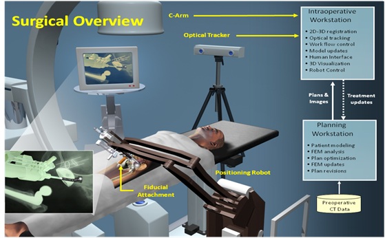 Osteolysis is a condition wherein bone breaks down, undergoes resorption, and dissolves into a viscous solution. In less-invasive treatment, the surgeon tries to remove osteolytic defects behind the acetabular cup using conventional rigid tools. However, complete treatment of the lesion cannot be achieved with this method. The BIGSS Lab is developing a minimally-invasive surgical workstation to treat the osteolysis behind the well-fixed cup during revision surgery. They have developed a Dexterous Snake-like Manipulator (SDM) for this purpose. This dexterous manipulator will be an active cannulae for guiding tools in a surgical workstation for the diagnosis, planning and real-time intra-operative treatment of the lesions. This project focuses on integrating the SDM with a 6 DOF Universal Robot (UR5) and position control of SDM inside the lesion.
 <fs large> Background and Specific Aims:</fs>
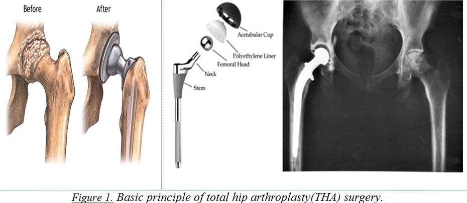
Wear of the articulating components (Figure 2.a) in a total hip arthroplasty (THA) surgery (Figure 1), typically a polyethylene liner, leads to formation of polyethylene particles that cause macrophage activation and osteolysis of the bone surrounding the implant (Figure 2.b). According to Figure 2.c, if this procedure left unmonitored and untreated eventually fracture and component loosening with catastrophic failure will occur.
Diagnosis and treatment of pelvic osteolysis is both challenging and complex , with multiple decision points depending on the extent of lesions and the degree to which the implant is well-fixed. The current less-invasive treatments have been shown to reliably fill less than half of the osteolytic defects behind the acetabular cup (Figure 2.b). Current manual tools are hard to manipulate precisely, and lack sufficient dexterity to permit surgeons reach all the lesion area. This clinical problem motivated the development of a novel system for this kind of surgeries.
APL has designed a cable driven SDM (Figure 3) to achieve the osteolytic lesions behind the cup without the removal of implants (less-invasive procedure) which has these specifications: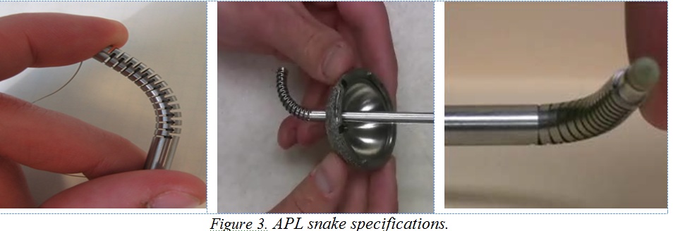
Planar manipulator composed of superelastic nitinol
4mm open lumen for inserting different tools in the SDM
Designed to fit in a hip implant (6mm OD)
<fs large>Overview of Goals</fs>
The BIGSS lab is developing a minimally-invasive surgical workstation (Figure 4) to treat the osteolytic lesions behind the well-fixed cup 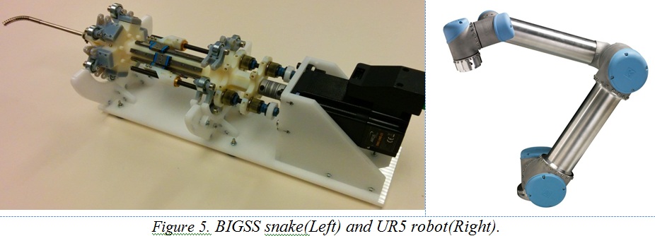 during revision surgery using the mentioned SDM. This dexterous manipulator will be an active cannulae for guiding tools in a surgical workstation for the diagnosis, planning and real-time intra-operative treatment of the lesions. According to Figure 4, the SDM will be positioned in the workspace by a robotic arm. The focus of this project is integrating the SDM with the robotic arm- which is a 6 DOF Universal Robot (UR5) - and position control of the tip of the SDM inside the lesion area. The SDM and UR5 robot are shown in Figure 5.
<fs large> Deliverables:</fs>
<fs medium>Minimum</fs>
• Deriving and implementing the kinematic equations of UR5
• Interfacing the SDM with UR5 (Mechanical design and fabrication)
• Coupled inverse control of robots outside the body
<fs medium>Expected</fs>
• Controlling the position of the coupled robots using virtual RCM when all of the SDM is in the body (Simulation and implementation)
<fs medium>Maximum</fs>
• Controlling the position of the coupled robots using virtual RCM when all of the SDM is not in the body (Simulation and implementation)
• Modeling the kinematics of SDM using solid mechanics or beam theory
<fs large>Technical Summary of Approach:</fs>
This project consists of four steps (Figure 6): 1) mechanical design for integrating SDM with UR5 robot.; 2) deriving the kinematics and other relevant equations for controlling the robot.; 3) understanding how to control the UR5 through the provided executables and libraries; 4) position control of the SDM which is the main focus of this work. We will use the results of other steps in this part. Following the detailed tasks of each part has been mentioned.
<fs medium>Part I: Mechanical Design</fs>
The main purpose is to interface the SDM with UR5. This task involves:
Preparing a 3-D model of the UR5 inside a CAD software
Mechanical interface of SDM to UR5 considering these limitations:
        1.	UR5 has a 5kg load limit
        2.	SDM lumen should be accessible
        3.	Modifying existing actuation unit
        4.	Considering work space of the UR5
Fabrication of mechanical parts
Assembly
<fs medium>Part II: Deriving and simulation of required kinematic equations of the SDM and UR5 with Matlab- Simmechanics</fs>
The Aim of this part is preparing required equation for controlling the SDM and verifying those equations through simulation. We will use SimMechanics for simulation of the robots (Figure 7). This model can be used for implementation of control algorithm before implementation on real robots.This video (ur5-simmech.wmv) is an example of this method. The tasks of this part are summarized as:
Deriving the Forward and Inverse Kinematics of the UR5 robot
Simulation of these Equations in Simmechanics-Matlab
Being familiar and working with the available kinematic model of the SDM
Simulation of the inverse kinematics of the coupled robots without considering physical limitation
<fs medium>Part III: Working with and setting up the UR5 robot</fs>
For implementing the control algorithm, we first should be able to work with UR5. Some tasks of this part are:
Controlling the UR5 using C or Python
Implementation of derived kinematic equations (Forward and Inverse)
Controlling the coupled robots without considering the physical limitation of the problem
 <fs medium>Part IV: Position Control of the end-effector</fs>
The final part and target of this project is controlling the position of SDM. However, for position control of the SDM we should consider these points:
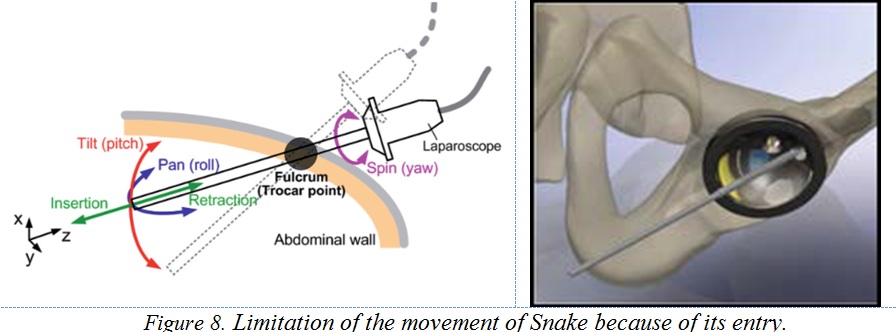
1. According to Figure 8 SDM entry is through the screw holes of acetabular cup therefore 2 degrees of freedom of the UR5 will be lost considering this constraint
2. 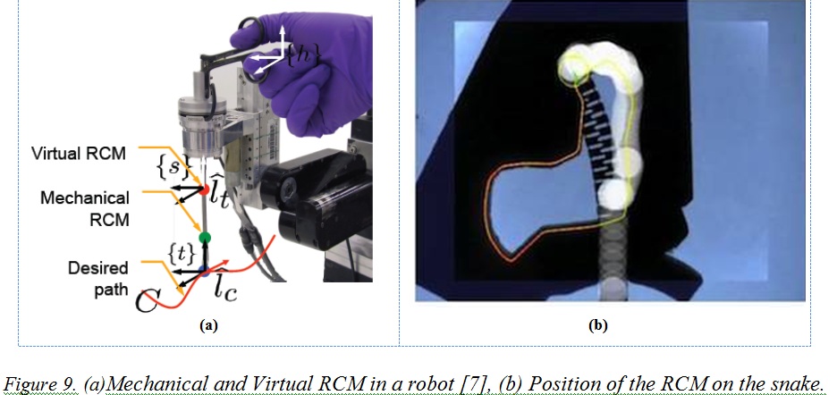 The UR5 robot has not a Mechanical RCM point therefore we should create a virtual RCM point. These RCMs are shown in Figure 9.a which is a work by A.Kapoor [7].
3. There may not be enough space inside the pelvis and behind acetabular cup therefore some parts of SDM may remain outside the acetabular cup during part of the procedure (Figure 9.b). The virtual RCM in this situation would be on the flexible part which is a curve not a line. For this case, we maybe can assume that the RCM is on a rigid body which is along with the SDM base.
4. We need the exact configuration of the robot after pulling the cables for controlling and determining the RCM (robot has not a constant curvature).
5. Lateral forces of the cup may change the derived kinematic equations of the SDM. We assume that there is not any lateral force in this work.
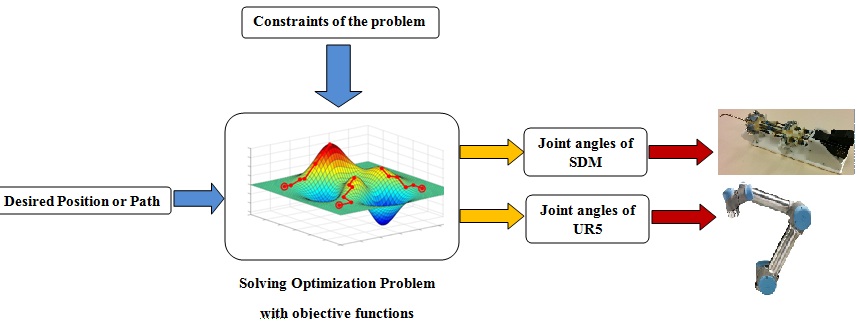
Regarding these assumptions and considerations we should use virtual fixture algorithms to control the SDM [5-9]. We will use optimization to find the joint angles of the actuators regarding our constraints like virtual RCM and limitation on actuators velocities. Figure 10 briefly describes the control algorithm block diagram.
<fs x-large>Check Point Results:</fs>
Simulation (UR5+Snake Actuation unit)
For solving the problem, first I considered the UR5 robot and its actuation unit which can be considered as a rigid rod attached to the UR5.In this problem we just need the Jacobian matrix of UR5+Rigid rod.
Simulation Goal: Tracking a desired circular path considering RCM constraint
Simulation (UR5+SDM unit):
For controlling the coupled robot, first we need to obtain the Jacobian matrix of the snake From differentiating the relation between cable length and tip position of the snake. Using a series of the tests relation between cable length and tip position of the snake has been derived by curve fitting technique.
Simulation Goal: Tracking a desired circular path considering RCM constraint and cable length limitation
<fs x-large>Mini Check Point Results:</fs>
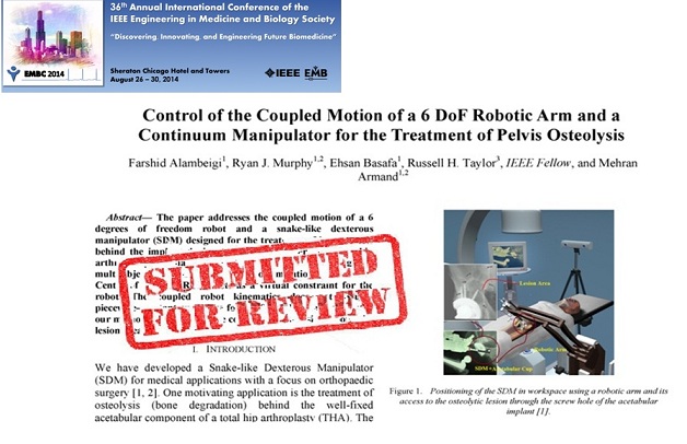
Submitting paper in IEEE EMBS Conference- April 07:
New Simulation considering working in confined space :
<fs larger>Mechanical interface of the SDM to the UR5:</fs>
<fs larger>Fabricated and assembled parts:</fs>
<fs large>Management Plan: Detailed Task Schedule</fs>
Last Update: 03/27/2014
Updated Management Plan: Detailed Task Schedule
Final Management Plan: Detailed Task Schedule
<fs large>Final Deliverable Status</fs>
<fs large>Management Plan: Basics</fs>
• Weekly meeting with mentors has been considered • I am planning to spend a total of 35 hrs per week on this project.
<fs large> Management Plan: Key Milestones</fs>
February 16: Simulation of the model in Simmechanics-Matlab
March 09: Mechanical interface of SDM to UR5
March 23: Working with and setting up the UR5 robot
March 23: Fabrication of first coupled robot
April 6: Controlling the coupled robots (Minimum Deliverable)
April 20: Simulation of virtual fixture (RCM point is not on the SDM)
April 27: Testing the algorithm on Robots (Expected Deliverable)
May 04: April Simulation of virtual fixture (RCM point is on the SDM)
May 04: Testing the algorithm on Robots (Maximum Deliverable)
May 09: Final report Presentation
<fs large> Updated Management Plan: Next Key Milestones(03/27/2014)</fs>
April 07: Submitting paper in IEEE Engineering in Medicine and Biology Society (EMBC’14)
April 13: Mechanical interface of SDM to UR5 (Minimum Deliverable)
April 23: Working with and setting up the UR5 robot
April 23: Fabrication of first coupled robot (Minimum Deliverable)
April 30: Testing the algorithm on Robots (Expected Deliverable)
May 04: April Simulation of virtual fixture (RCM point is on the SDM)
May 04: Testing the algorithm on Robots (Maximum Deliverable)
May 09: Final report Presentation
<fs medium> Mechanical design:</fs>
• 3D model of the SDM: Dr. Armand will give me this model.
• Machine shop and 3D printer for fabricating the interface parts: JHU and APL tools can be used using Dr. Armand or Ryan Murphy.
If we cannot access to the machine shop or cannot fabricate the part then we should do our works in simulation and Simmechanics.
<fs medium> Robots:</fs>
• UR5 robot: BIGSS lab will buy this robot before March 1.
• SDM robot: I can use the BIGSS lab 2-D SDM.
If we cannot buy the UR5 then we should do our works in simulation and Simmechanics.
<fs medium>Kinematic model of SDM:</fs>
• I will use the available model of Ryan Murphy.
<fs medium> Access to Mentors:</fs>
• Weekly meeting with Dr. Armand and Ryan Murphy
• Scheduled meeting with Dr. Taylor as needed
Reading List & Bibliography
[1] R.J. Murphy, M.D.M. Kutzer, G.S. Chrikijian, M. Armand, Constrained workspace generation for snake-like manipulators with applications to minimally invasive surgery, in Proceedings of the 2013 IEEE International Conference on Robotics and Automation, pp. 5341–5347, May 2013.
[2] R.J. Murphy, MDM Kutzer, SM Segreti, BC Lucas, M Armand., Design and kinematic characterization of a surgical manipulator with a focus on treating osteolysis. Robotica, 2013.
[3] Segreti, S.M.; Kutzer, M.D.M.; Murphy, R.J.; Armand, M. “Cable length estimation for a compliant surgical manipulator,” IEEE International Conference on Robotics and Automation (ICRA), 2012, pp.701-708.
[4] M. D. M. Kutzer, S. M. Segreti, C. Y. Brown, R. H. Taylor, S. C.Mears, and M. Armand, “Design of a new cable-driven manipulator with a large open lumen: Preliminary applications in the minimallyinvasive removal of osteolysis,” in IEEE International Conference on Robotics and Automation(ICRA), 2011
[5] A. Kapoor, M. Li, and R. H. Taylor “Constrained Control for Surgical Assistant Robots,” in IEEE Int.Conference on Robotics and Automation, Orlando, 2006, pp. 231-236.
[6] A. Kapoor and R. Taylor, “A Constrained Optimization Approach to Virtual Fixtures for Multi-Handed Tasks,” in IEEE International Conference on Robotics and Automation (ICRA), Pasadena, 2008, pp. 3401-3406.
[7] A. Kapoor, M. Li, and R. H. Taylor “Spatial Motion Constraints for Robot Assisted Suturing using Virtual Fixtures”, in Medical Image Computing and Computer Assisted Intervention,Palm Springs, 2005.
[8] A. Kapoor, K. Xu, et al. “Telemanipulation of Snake-Like Robots for Minimally Invasive Surgery of the Upper Airway’’.
[9] M. Li, M. Ishii, and R. H. Taylor, “Spatial Motion Constraints in Medical Robot Using Virtual Fixtures Generated by Anatomy,” IEEE Transactions on Robotics, vol. 2, pp. 1270-1275, 2006. [10] P.Routray, A. Kumar, “Interfacing APL Snake End Effector to LARS Robot”, CIS II project, 2013.
Here give list of other project files (e.g., source code) associated with the project. If these are online give a link to an appropriate external repository or to uploaded media files under this name space.